Bar codes🔗
About linear (1D) bar codes🔗
More Info
Learn about reading bar codes and many other topics in interactive online courses at our MVTec Academy.
A bar code consists of several dark bars and bright spaces.
For every bar code, there is a smallest possible element, the narrowest possible bar or the narrowest possible space, which is called
In general, the width of the bars and spaces is different, but always a multiple of the module.
Several bars and spaces together form a pattern.
This pattern encodes a symbol defined in a decoding table.
The conventions how such a binary pattern encodes a symbol and the corresponding decoding table lead to the respective bar code type.
In addition to the patterns encoding the symbols, there are also patterns with special tasks.
Depending on the type, there are further patterns, which can or must be part of the bar code:
- Quiet zone
-
Zone in which no edges may occur. This zone is required before the start character and after the stop character to find the code.
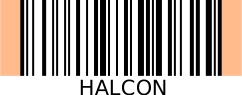
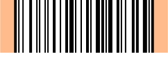
Figure 1. Schematic representation of the
- Start and stop pattern
-
Defining start, stop, and direction, these patterns make it possible to read and decode the code from left to right as well as from right to left (and thus upside down).

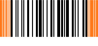
Figure 2. Schematic representation of the start and stop pattern (orange) using an example bar code of type Code 128
- Checksum
-
A digit that serves as a security check to ensure the code has been read correctly.

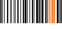
Figure 3. Schematic representation of the checksum (orange) using an example bar code of type Code 128
- Guard pattern
-
Specific pattern, which can occur on the left, right, or in the center as additional symbol.
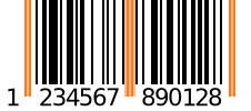
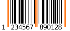
Figure 4. Schematic representation of a guard pattern (orange) using an example bar code of type UPC-A
- Finder patterns
-
Pattern used to locate the symbol.
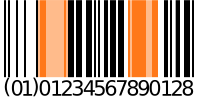
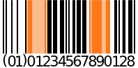
Figure 5. Schematic representation of a
- Add-on symbol
-
Additional symbols for encoding supplementary information. These symbols are encoded as bar codes with restricted length.
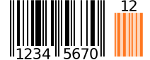
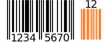
Figure 6. Schematic representation of an add-on symbol (orange) using an example bar code of type EAN-8 Add-On 2
About composite bar codes🔗
Composite bar codes consist of the following elements:
- Linear bar code
- See description above.
- Data Code
- For more information about data codes, see Data codes.
- Linking pattern
-
Combines the two codes mentioned before.
The following figure shows a schematic representation of a composite bar code.
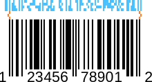
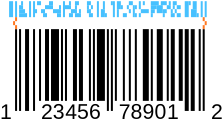
Figure 7. Schematic representation of a composite bar code using an example bar code of type UPC-A Composite:
Linear bar code (black), data code (light blue), and the linking pattern (orange).
Reading bar codes🔗
To be able to read a bar code in an image, the bar code must be found first. The regions in which HALCON assumes a bar code are called candidates.
To read a candidate, different lines are laid through the region, called scanlines.
Although theoretically a single scanline could be sufficient, one tries to decode the bar code along all scanlines.
This increases the chance of decoding the code correctly.
In addition, several successfully decoded scanlines allow additional plausibility checks, i.e., reading several scanlines equally decreases the chance of false positives.
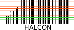
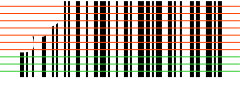
Figure 8. Schematic representation of different scanlines of a candidate. Certain scanlines were read successfully (green), while the reading failed for others (red).