Optimization for structured light🔗
Setting up the measurement🔗
If you want to achieve accurate results, please follow the recommendations given in this section:
- The resolution of the projector should at least be the same as the resolution of the camera.
- The gray value range of the captured camera image should be exploited as fully as possible. I.e., in the ideal case the gray values of the camera image would be near 0 if the screen is black while the gray values would be near 255 (in case of byte camera images) if the screen is white.
- For some objects (e.g., white glossy plastic) it is difficult to get a good contrast between the stripes and the background. In this case it helps to increase the gain value of the camera. Furthermore, when only a binary pattern (e.g., gray code) is used, one can consider setting the camera gamma value to a value larger 1 in order to increase the contrast.
- If you are using a color camera, choose the channel with the best contrast.
- The gray values of the camera image should depend nearly linearly on the gray values of the screen.
This can be achieved with a radiometric calibration.
See e.g., the example program
%HALCONEXAMPLES\%/hdevelop/Calibration/Self-Calibration/radiometric_self_calibration.hdev. - There should be no overexposed regions if a completely white image is displayed on the screen (at least in the image part where the measuring object is located).
- The camera should be focused on the object, but also the stripe patterns should be in focus. This means that the depth of field of the camera should be high enough. In order to optimize the available depth of field, consider positioning the screen closer to the object surface.
- As a rule of thumb concerning the minimal size of the defects in the camera image: As a minimum we recommend one size being in the order of magnitude of 10 pixels.
- The stripe width of the projected pattern (
'min_stripe_width') should be chosen such that the smallest stripes are visible with distinct edges in the camera image. - The ambient light should be low, especially if objects are partially specular.
- The background behind the measuring object should be non-specular.
- The monitor or projector should be synchronized with the camera.
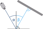
- In the deflectometry case, arrange measuring object, camera, and pattern source such that the camera captures the reflection of the screen that is visible in the whole surface part under inspection. The angles of the camera and the monitor/diffusor plate should have similar absolute values. More precisely, the angles mentioned are the angle between the camera viewing direction and the normal of the flat surface (\(\alpha\)) or the angle between the normal of the monitor/diffusor plate and the normal of the flat surface (\(\beta\)). See the illustration in Figure 1. The sensitivity of the surface inspection can be improved if the mentioned angles are increased. Nevertheless, this is a theoretical consideration and from a practical point of view a modified setup may require a fairly larger monitor/diffusor plate.
- In the deflectometry case, the needed area size of the projected pattern (monitor/diffusor plate) depends on the surface area and surface curvature to be inspected. The stronger the curvature the larger the projector needs to be.
Checking the decoding results🔗
Decoding of camera images relies upon being able to know whether a pixel is in a region where a light stripe is reflected or where a dark stripe is reflected.
You can check whether the algorithm recognizes bright and dark regions correctly by inspecting the ‘binarized image’ obtained from get_structured_light_object.
Note that for this the ‘persistence’ mode has to be enabled with set_structured_light_model_param before decoding.
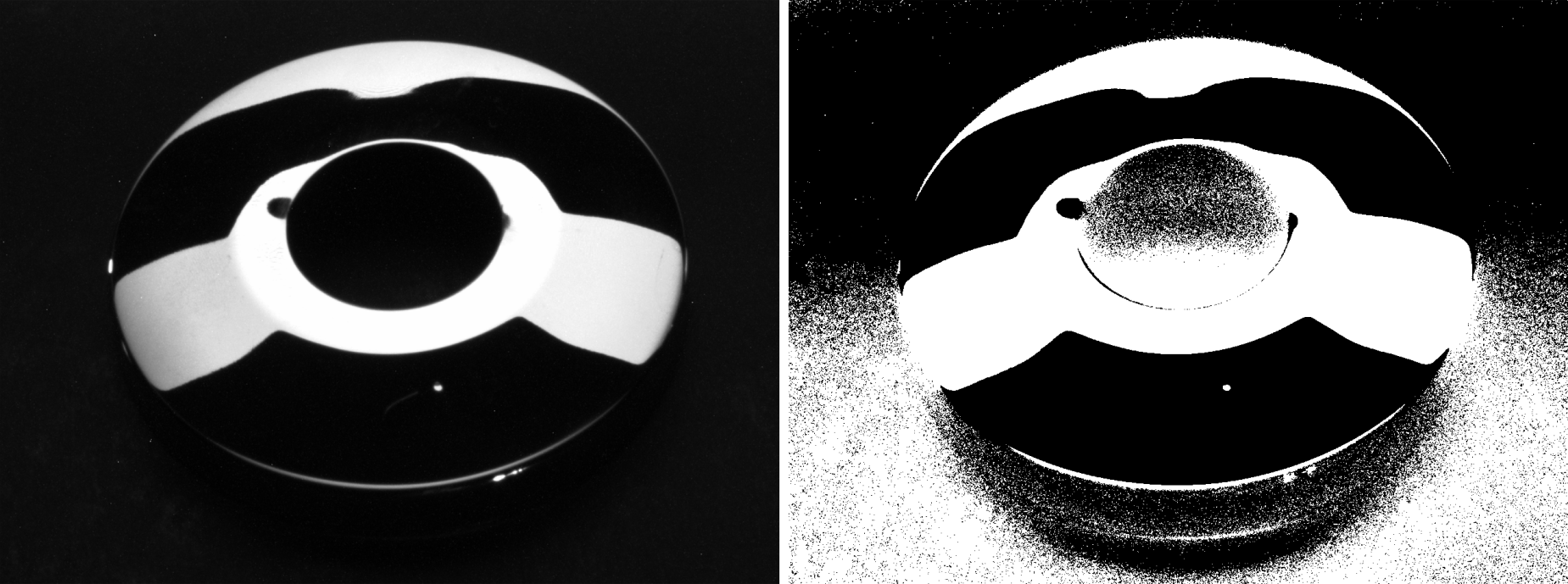
An exemplary camera image compared to its binarized image is shown in Figure 2. The white or black regions in the binarized image indicate that the camera pixel observed reflections of white or black regions of the projected pattern. The binarized image below shows white and dark regions that have been recognized correctly.
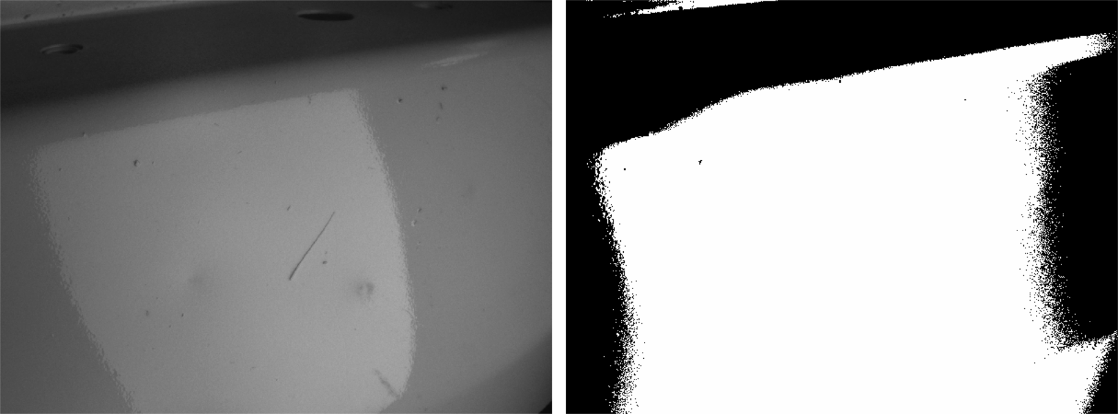
For comparison, Figure 3 shows a partially specular surface and its corresponding binarized image.
Several pixels have been identified wrongly, i.e. some actually dark pixels have been identified as bright pixels.
Therefore dark regions of the camera image are bright regions in the binarized image which is an indication for partially specular surfaces.
To optimize the decoding results, we recommend the pattern type 'single_stripe' in case of partially specular surfaces.
To help you deciding whether the bright or the dark regions were correctly encoded, you can use the procedure structured_light_inspect_segmentation.
This procedure helps to validate the decoded bright or dark areas in the Gray code image in comparison to the bright or dark areas in the camera image.
The procedure can thus be used to find a suitable value for the parameter 'min_gray_difference'.
Please open the HDevelop program %HALCONEXAMPLES\%/hdevelop/Inspection/Structured-Light/structured_light_partically_specular.hdev for an example how to use this procedure.
Another way to improve the reliability of the camera images is to use the procedure compute_structured_light_modulation to compute the modulation image.
A threshold operation can than be applied to the modulation image to eliminate outliers.
This approach is particularly useful for 3D reconstruction and is for instance shown in the example program %HALCONEXAMPLES\%/hdevelop/3D-Reconstruction/Structured-Light/structured_light_3d_surface_reconstruction.hdev.
Synchronizing the camera with the pattern source🔗
The synchronization of the camera with the source generating the light pattern depends strongly on the source. The two main cases are explained in the following.
Synchronizing the camera with the monitor🔗
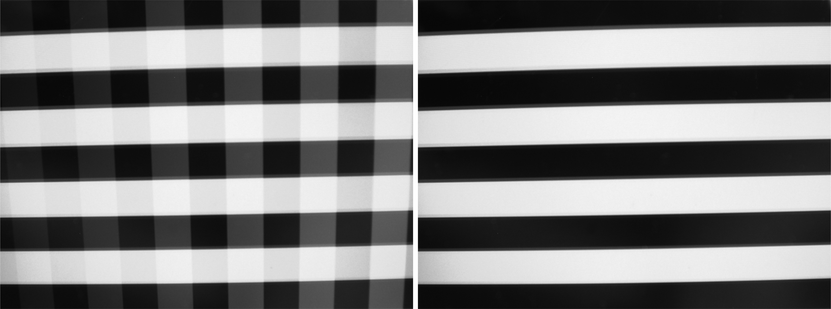
Each pattern image needs to be already fully displayed on the monitor when the exposure time for the corresponding camera image begins. Otherwise, (parts of) the previous pattern image may still be visible when a new camera image is acquired. An example is shown in Figure 4.
A simple way to prevent overlapping patterns is to include a short waiting period after disp_image before grab_image is called.
The correct waiting period depends on the used setup and needs to be found by trial and error.
For convenience, HALCON provides the procedure structured_light_camera_screen_sync that helps finding a suitable waiting period.
To use this procedure, the camera should be positioned such that it sees a large part of the monitor where the pattern images are to be displayed.
Alternatively, the camera can observe the reflection of the monitor via a planar mirror.
The procedure alternately displays images with vertical and horizontal stripes and acquires the corresponding camera images.
The waiting period between the call to disp_image and the call to grab_image can be set by the user.
In the camera images there should be no visible overlap of consecutive pattern images as in Figure 4 on the left.
Furthermore, you should check that each camera image shows the correct pattern. In a badly configured setup, a camera image might be acquired while the previous pattern is still fully displayed. In that case, the n-th image would show the (n-1)-th pattern image. If any of the these problems occur, a longer waiting period should be tested. Otherwise, you can try whether a shorter waiting period is still sufficient.
Synchronizing the camera with the projector🔗
Projectors typically have a digital output for providing hardware triggers for cameras. As soon as an image is displayed the projector emits a digital signal which can be used for synchronizing the acquisition of the image by the camera.
Speeding up the acquisition for structured light🔗
For a more time-efficient acquisition process, the exposure of each camera image should be triggered the moment the corresponding pattern image is fully visible on the screen. We summarize two possible hardware-based solutions:
Using a monitor🔗
Position two photosensors on a small area of the monitor that is not reflected by the inspected object towards the camera. The sensors should detect whenever the pixel values at their position switch from black to white and trigger the camera at each detection.
Adapt the pattern images that are displayed on the monitor such that they alternate between white and black pixel values in the area where the sensors are positioned.
Whenever the area of the first sensor is white, the area of the second sensor should be black and vice versa.
This can be done using the operators paint_region or overpaint_region.
This way, whenever a new pattern image is displayed on the monitor, one of the sensors sends a trigger signal to the camera and the camera image is acquired at the right moment. As a monitor-refresh usually occurs from the top to the bottom of the monitor, it is recommended to position the sensors at the bottom of the display area. This should ensure that the sensor is not triggered before the pattern image is fully displayed.
Using a projector🔗
Industrial projectors have the advantage that the image projection can be realized faster compared to structured light projection by standard TFT monitors. One reason for that is the long fade-out characteristic of monitors. Another reason is that projectors typically have a digital output for providing hardware triggers for cameras.