Instance segmentation and object detection🔗
With object detection we want to find the different instances in an image and assign them to a class. The instances can partially overlap and still be distinguished as distinct. This is illustrated in Figure 1.
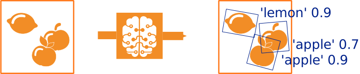
Figure 1. Possible example for object detection: Within the input image, three instances are found and assigned to a class.
Instance segmentation is a special case of object detection, where the model also predicts an instance mask marking the specific region of the instance within the image. This is illustrated in Figure 2.
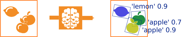
Figure 2. Possible example for instance segmentation: Within the input image, three instances are found. Each instances is assigned to a class and obtains a mask marking its particular region.
In general, explanations for object detection also apply to instance segmentation. Possible differences are brought up in the specific sections.
Object detection leads to two different tasks – finding the instances and classifying them. In order to do so, we use a combined network consisting of three main parts:
-
Part 1, called backbone, consists of a pretrained classification network. Its task is to generate various feature maps, so the classifying layer is removed. These feature maps encode different kinds of information at different scales, depending how deep they are in the network. Thereby, feature maps with the same width and height are said to belong to the same level.
For more information, see also About the network and the training process on the Deep learning overview page. -
In part 2, backbone layers of different levels are combined. More precisely, backbone levels of different levels are specified as docking layers, and their feature maps are combined. As a result, we obtain feature maps containing information of lower and higher levels. These are the feature maps we will use in the third part. The second part is also called feature pyramid and, together with the first part, it constitutes the feature pyramid network.
-
Part 3 consists of additional networks, called heads, for every selected level. They get the corresponding feature maps as input and learn how to localize and classify potential objects. Additionally, this third part includes the reduction of overlapping predicted bounding boxes.
An overview of the three parts is shown in Figure3.
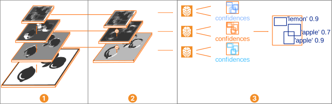
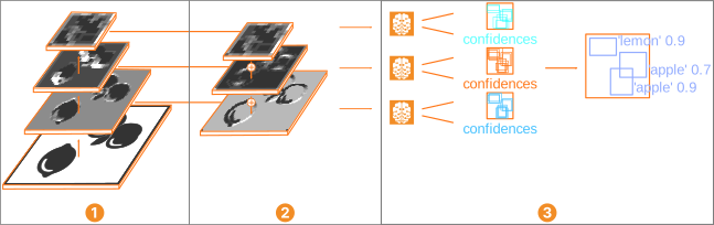
Figure 3. Schematic overview of the mentioned three parts:
Backbone
Backbone feature maps are combined and new feature maps generated.
Additional networks, called heads, which learn how to localize and classify potential objects.
Overlapping bounding boxes are suppressed.
About anchors and bounding boxes🔗
Let us take a look what happens in the third part
.
In object detection, the location in the image of an instance is given by a rectangular bounding box.
Hence, the first task is to find a suiting bounding box for every single instance.
To do so, the network generates reference bounding boxes and learns how to modify them to fit the instances best possible.
These reference bounding boxes are called anchors.
The better these anchors represent the shape of the different ground truth bounding boxes, the easier the network can learn them.
For this purpose, the network generates a set of anchors on every anchor point, thus on every pixel of the used feature maps of the feature pyramid.
Such a set consists of anchors of all combinations of shapes and sizes, and for instance type 'rectangle2' (see below) also orientations.
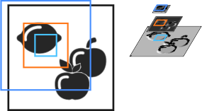
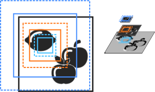
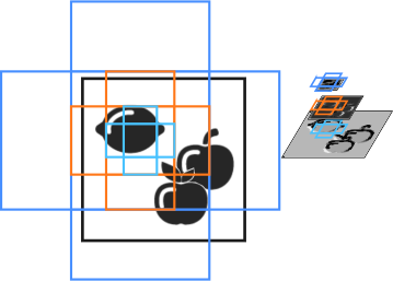
The shape of those boxes is affected by the parameter 'anchor_aspect_ratios', the size by the parameter 'anchor_num_subscales', and the orientation by the parameter 'anchor_angles' (see Figure 4 and get_dl_model_param).
If the parameters generate multiple identical anchors, the network internally ignores those duplicates.
 |
 |
 |
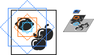 |
Figure 4. Schema for anchors in the feature map (right) and in the input image (left).
Anchors are created on the feature maps of different levels, for example, the ones drawn (in light blue, orange, and dark blue).
Anchors of different sizes are created setting 'anchor_num_subscales'.
Anchors of different shapes are created setting 'anchor_aspect_ratios'.
Anchors of different orientations are created setting 'anchor_angles' (only for instance type 'rectangle2').
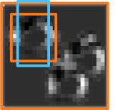
The network predicts offsets how to modify the anchors in order to obtain bounding boxes fitting the potential instances better. The network learns this with its bounding box heads, which compare the anchors generated for their level with the corresponding ground truth bounding boxes, and thus the information about where the single instances are in the image. An illustration is shown in Figure 5.
 |
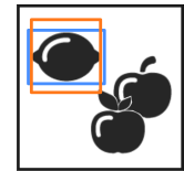 |
Figure 5. Bounding box comparisons, illustrated for instance type 'rectangle1'.
Network modifying the anchor (light blue) to predict a better fitting bounding box (orange)
During training, the predicted bounding box (orange) are compared with the most overlapping ground truth bounding box (blue) so the network can learn the necessary modifications.
As mentioned before, feature maps of different levels are used.
Depending on the size your instances have in comparison to the total image, including early feature maps (where the feature map is not very compressed and therefore small features are still visible) and deeper feature maps (where the feature map is very compressed and only large features are visible) is beneficial or not.
This can be controlled by the parameters 'min_level' and 'max_level', which determine the levels of the feature pyramid.
With these bounding boxes, we have the localization of a potential instance, but the instance is not classified yet.
Hence, the second task consists of classifying the content of the image part within the bounding boxes.
This is done by the class heads.
For more information about classification in general, see Classification.
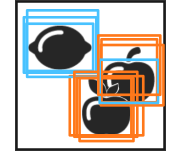
Most probably the network will find several promising bounding boxes for a single object.
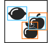
The reduction of overlapping predicted bounding boxes is done by non-maximum suppression, set over the parameters 'max_overlap' and 'max_overlap_class_agnostic' when creating the model or using set_dl_model_param afterwards.
An illustration is shown in Figure 6.
 |
 |
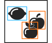 |
Figure 6. Suppression of significant overlapping bounding boxes, illustrated for instance type 'rectangle1'.
Network finding several promising instances for the class apple (orange) and lemon (blue)
Suppression of overlapping instances assigned to the same class is set by 'max_overlap'.
Overlapping instances of different classes are not suppressed.
Using the parameter 'max_overlap_class_agnostic', also strongly overlapping instances of different classes are suppressed.
As output, you get bounding boxes proposing possible localizations of objects and confidence values, expressing the affinity of this image part to one of the classes.
In case of instance segmentation, a further part follows. An additional head receives the feature map parts corresponding to the predicted bounding boxes as input. From there, it predicts a (class-agnostic) binary mask image. This mask marks the region within the image belonging to the predicted instance. Figure 7 gives a schematic overview.
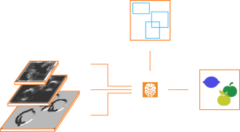
Figure 7. Schematic overview of the mask prediction. It uses the parts shown in the overview of the three parts of an object detection network from above.
More Info
- In HALCON, classification with deep learning is implemented within the more general deep learning model. For more information about the latter, see HALCON DL model.
- For the specific system requirements to apply deep learning, see Requirements for deep learning and deep-learning-based methods.
About data🔗
We distinguish between data used for training and evaluation and data used for inference.
While the latter consists of bare images, for the former you provide the information defining, for each instance, which class it belongs to and where it is in the image (via its bounding box).
For instance segmentation, the pixel-precise region of the objects is needed, provided via the masks.
As a basic concept, the model handles data over dictionaries, meaning it receives the input data over a dictionary DLSample and returns the dictionaries DLResult and DLTrainResult.
For more information about data handling, see HALCON DL model.
- Data for training and evaluation
-
The dataset consists of images and corresponding information. They have to be provided in a way the model can process them. For more information about the image requirements, see Images below.
The training data is used to train and evaluate a network for your specific task. With the aid of this data, the network can learn which classes are to be distinguished, what such examples look like, and how to find them. The necessary information is provided by specifying, for each object in every image, to which class the object belongs and where it is located. This is done by providing a class label and an enclosing bounding box for every object.
For instance segmentation, additionally a mask is needed for every instance.How to store and retrieve this information is possible in different ways. For information about how to format the data, see HALCON DL model. In short, a dictionary
DLDatasetserves as a database for the information needed by the training and evaluation procedures.Tip
You can label your data and directly create the dictionary
DLDatasetin the respective format using the MVTec Deep Learning Tool, available from the MVTec website.If you have your data already labeled in the standard COCO format, you can use the procedure
read_dl_dataset_from_coco(for'instance_type'='rectangle1'only). It formats the data and creates a dictionaryDLDataset. For more information about the needed part of the COCO data format, see the documentation of the procedure.You also want enough training data to split it into three subsets: for training, for validation, and for testing the network. These subsets are preferably independent and identically distributed (see also About data splitting).
For object detection, the network has to learn how to find possible locations and sizes of the instances. That is why also instance locations and their sizes need to appear representatively in your training dataset.
- Images
-
Regardless of the application, the model poses requirements on the images, such as the dimensions, the gray value range, and the type. The specific values depend on the network itself and can be queried with
get_dl_model_param. For more information about specific values of different models, seeread_dl_model.To fulfill these requirements, you may have to preprocess your images. Standard preprocessing is implemented in the procedure
preprocess_dl_datasetand, for a sample, inpreprocess_dl_samples. In case of custom preprocessing, these procedures offer guidance on the implementation. - Bounding boxes
-
Depending on the instance type of object detection model, the bounding boxes are parametrized differently:
-
Instance type
'rectangle1'The bounding boxes are defined over the coordinates of upper left corner (
'bbox_row1','bbox_col1') and the lower right corner ('bbox_row2','bbox_col2').
This is consistent withgen_rectangle1. -
Instance type
'rectangle2'The bounding boxes are defined over the coordinates of their center (
'bbox_row','bbox_col'), the orientation'bbox_phi', and the half edge lengths'bbox_length1'and'bbox_length2'. The orientation is given in arc measure and indicates the angle between the horizontal axis and'bbox_length1'(mathematically positive).
This is consistent withgen_rectangle2.
If in case of
'rectangle2'you are interested in the oriented bounding box, but without considering the direction of the object within the bounding box, set the parameter'ignore_direction'to'true'. This is illustrated in Figure 8 below.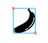
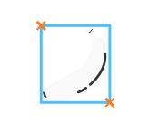



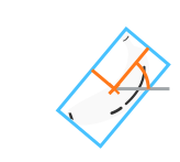
Figure 8. Bounding box formats of the different object detection instance types:
Instance type'rectangle1'
Instance type'rectangle2', where the bounding box is oriented towards the banana end
Instance type'rectangle2', where the oriented bounding box is of interest without considering the direction of the banana within the bounding box -
- Mask
-
Instance segmentation requires a mask for every object to be learned, in addition to a tight bounding box. Such a mask is given as a region. These regions are given with respect to the image.
The masks for a single image are given as an object tuple of regions; see Figure 9 below. The order of the masks corresponds to the order of the bounding box annotations.
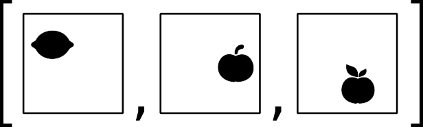

Figure 9. Masks of an image: Tuple containing an independent region for every object to be learned
- Model output
-
The network output depends on the task:
-
Training
As output, the operator
train_dl_model_batchwill return a dictionaryDLTrainResultwith the current value of the total loss as well as values for all other losses included in your model. -
Inference and evaluation
As output, the operator
apply_dl_modelwill return a dictionaryDLResultfor every image.For object detection, this dictionary will include, for every detected instance, its bounding box, the confidence value of the assigned class, and its mask in the case of instance segmentation. Several instances may be detected for the same object in the image; see the explanation of the non-maximum suppression in About anchors and bounding boxes above. The resulting bounding boxes are parametrized according to the instance type (as specified via
'instance_type') and given in pixel centered sub-pixel accurate coordinates.More Info
- For more information about the coordinate system, see About coordinate systems in HALCON.
- For more information about the output dictionary, see HALCON DL model.
-
Model parameters and hyperparameters🔗
Apart from the general DL hyperparameters explained on the Deep Learning page, there are further hyperparameters relevant for object detection:
'bbox_heads_weight''class_heads_weight''mask_head_weight'(instance segmentation only)
These hyperparameters are explained in more detail in get_dl_model_param and set using create_dl_model_detection.
For an object detection model, there are two different types of model parameters:
-
Parameters defining your architecture.
Once your model is created, these settings cannot be changed. These parameters are all set using the operatorcreate_dl_model_detectionwhen creating your model. -
Parameters influencing your predictions and, as a consequence, the evaluation results. These parameters only relevant for object detection are
'max_num_detections''max_overlap''max_overlap_class_agnostic''min_confidence'
They are explained in more detail in
get_dl_model_param. To set them, you can usecreate_dl_model_detectionwhen creating your model or useset_dl_model_paramafterwards.
Evaluation measures🔗
For object detection, the following evaluation measures are supported in HALCON.
Note
To be able to compute such a measure for an image, the related ground truth information is needed.
- Mean average precision (
mAP) and average precision (AP) of a class for an IoU threshold (ap_iou_classname) -
The AP value is an average of maximum precision at different recall values. In simple terms, it indicates whether the predicted objects for this class are generally correct detections. In this context, we pay more attention to the predictions with high confidence values. The higher the value, the better.
We want both the correct top-1 classification and localization to count a prediction as a hit. The measure telling us the correctness of the localization is the intersection over union (IoU): An instance is considered correctly localized if its IoU is greater than the required threshold. Hence, the AP value depends on the class and on the IoU threshold.
For more information about the IoU, see Understanding the IoU below.You can obtain the specific AP values: the averages over the classes, the averages over the thresholds, and the averages over both the classes and the thresholds. The latter is the mean average precision (mAP), a measure of how well images are classified.
- True positives, false positives, false negatives
-
The concept of true positive, false positives, and false negatives is explained in Deep Learning. It applies for object detection with the exception that there are different kinds of false positives, for example:
- An instance was classified wrongly.
- An instance was found where there is only background.
- An instance was localized badly, meaning the IoU between the instance and its ground truth is lower than the evaluation IoU threshold.
- There is a duplicate, thus at least two instances overlap mainly with the same ground truth bounding box, but they overlap not more than
'max_overlap'with each other, so none of them was suppressed.
Important
To be able to access these values, enable detailed evaluation by setting the parameter
detailed_evaluationto'true'in theevaluate_dl_modelprocedure. - Score of Angle Precision (SoAP)
-
The SoAP value is a score for the precision of the inferred orientation angles. This score is determined by the angle differencesbetween the inferred instances (I) and the corresponding ground truth annotations (GT):
\[\begin{eqnarray*} \textrm{SoAP} = 1.0 - \frac{1}{\pi\, k} \sum_{k} \left| \varphi_{k}^{\textrm{I}} - \varphi_{k}^{\textrm{GT}} \right| \end{eqnarray*}\]where the index \(k\) runs over all inferred instances. This score only applies for detection models of instance type
'rectangle2'.
Understanding the IoU🔗
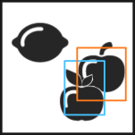
The intersection over union (IoU) is a measure for the accuracy of an object detection. For a proposed bounding box, it compares the ratio between area of intersection and the area of overlap with the ground truth bounding box. The figure below shows an example.
 |
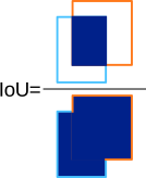 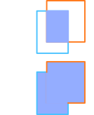 |
Figure 10. Visual example of the IoU, illustrated for instance type 'rectangle1'
Input image with ground truth bounding box (orange) and predicted bounding box (light blue)
IoU as the ratio between the area intersection and the area overlap
Note
In case of instance segmentation, the IoU is calculated based on the masks by default. It is possible to change the default and use the bounding boxes instead.