About coordinate systems in HALCON🔗
To specify a location in an image, we need a convention how to do so. Such a convention is set via a coordinate system. HALCON uses different coordinate systems. Here, we explain the ones used in two dimensions.
As pixels are discrete, to address them, we need a coordinate system using only integer values, the pixel coordinate system. For a higher accuracy that goes beyond the pixel grid, we need floating point coordinates, for example: \((3.6,4.1)\). This leads to subpixel accurate coordinate systems.
In HALCON, there are three different implementations of subpixel coordinate systems:
- Pixel centered coordinates, the HALCON standard subpixel coordinate system
- Edge centered coordinates
- Polar coordinates
Of the above, only the coordinate origin differs between the first two, as shown in the figures below. Calibration makes it possible to map the image coordinates distances to real-world distances.\
HALCON standard coordinate system🔗
- Pixel-accurate coordinate system
-
The pixel coordinate system treats the image as a grid of discrete elements, the pixels. In HALCON, we put the origin \((0,0)\) in the middle of the upper left pixel. Now, we assign the pixel coordinates specifying its row and column like in a matrix.
For an image of size height \(\times\) width \(= m \times n\) pixels this implies that the row coordinate values run from \(0\) to \(m-1\) and the column coordinate values from \(0\) to \(n-1\), as visualized in the figure below.
- Subpixel-accurate coordinate system – pixel centered
-
The origin of this coordinate system is in the center of the upper left image pixel. The axes are in row (r) and column (c) direction, respectively. Hence, this convention embeds the pixel coordinate system.
The upper left image corner has the coordinates \((-0.5,-0.5)\). For an image of size height \(\times\) width \(= m \times n\) pixels, the bottom right corner has the coordinates \((m-0.5,n-0.5)\) (\(= (m-1+0.5,n-1+0.5)\), as the coordinate values start at 0). It also implies that a pixel \((k,l)\) covers the area of the rectangle \((k-0.5,l-0.5), (k+0.5,l-0.5),\) \((k-0.5,l+0.5),\) \((k+0.5,l+0.5)\).
This convention is called the standard coordinate system or image coordinate system.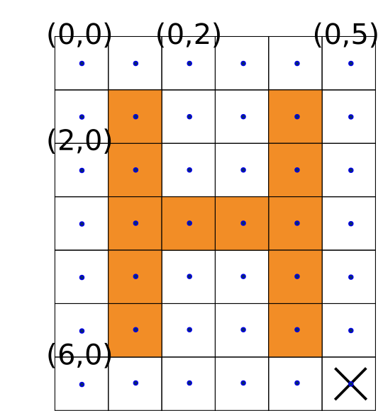
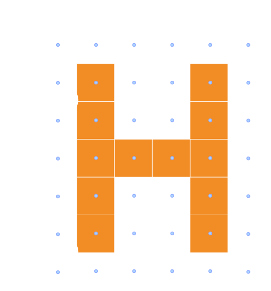
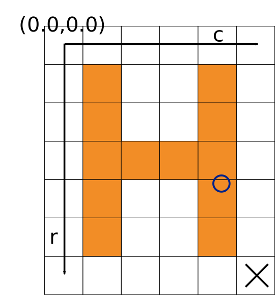
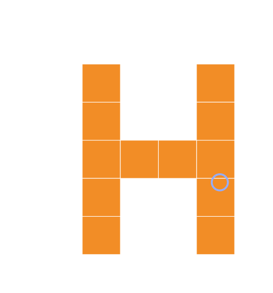
Figure 1. Visualization of the HALCON standard pixel and subpixel Cartesian coordinate systems
The center of the cross indicating the pixel in the bottom right corner has the coordinates:
\((6,5)\) (in pixel coordinates)
\((6.0, 5.0)\) (in standard subpixel coordinates). The circle center has the coordinates \((3.6,4.1)\).
HALCON non-standard Cartesian coordinate system🔗
If we rotate an image around its origin by \(\pi/2\) (90 degrees), we want the two images to have touching edges but not overlap. Further, scaling the image is not expected to result in negative image coordinates. Therefore, the origin \((0.0,0.0)\) has to be set in an image corner. This motivates the following coordinate system.
- Subpixel-accurate coordinate system – edge centered
-
For this coordinate system, we set the origin \((0.0,0.0)\) in the upper left image corner. Thus the center of the upper left pixel has the coordinates \((0.5,0.5)\) and for an image of size height \(\times\) width \(= m \times n\) pixels, the bottom right corner has the coordinates \((m,n)\).
A pixel \((k,l)\) covers the area of the rectangle \((k,l), (k,l+1),\) \((k+1,l), (k+1,l+1)\).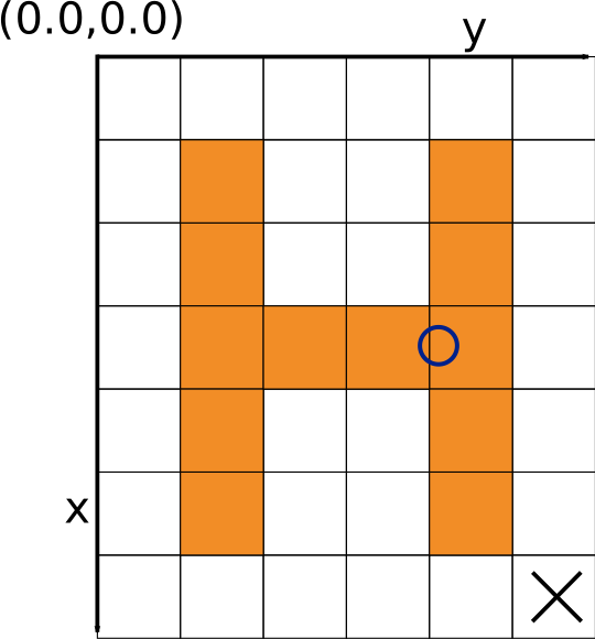
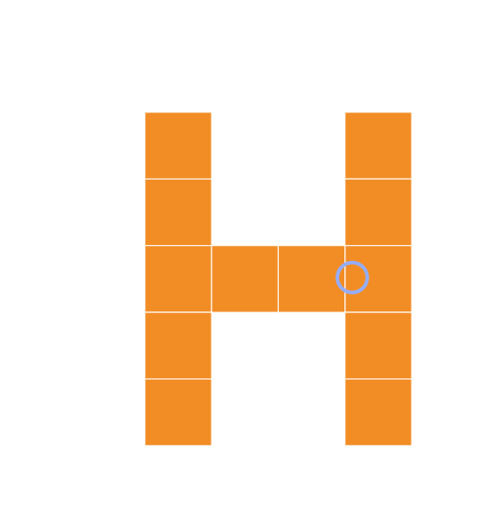
Figure 2. Visualization of the HALCON non-standard subpixel Cartesian coordinate system
The center of the cross indicating the pixel in the bottom right corner has the coordinates \((6.5,5.5)\). The circle center has the coordinates \((3.6,4.1)\).In this coordinate system, rotations are defined in the mathematically positive direction and thus counterclockwise. A rotation of \(\pi/2\) (90 degrees) maps the first axis (x-axis) onto the second axis (y-axis). Accordingly, the axes have the assignment row: x coordinate, column: y coordinate.
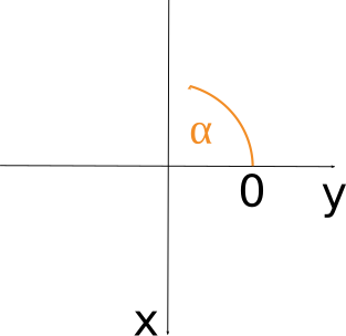
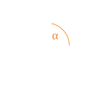
Figure 3. Visualization of a rotation (\(\alpha\)) using the edge-centered coordinate system
Operators expecting parameters in any Cartesian coordinate system🔗
The operator affine_trans_point_2d applies the transformation given by HomMat2D to the point coordinates.
This means, affine_trans_point_2d works in both Cartesian coordinate systems, as long you make sure that the point and the transformation are given in the same coordinate system.
The operators angle_ll and angle_lx may take the input points in pixel centered coordinates, but the returned angle is in the convention of rotations in a mathematically positive direction, thus counterclockwise, and with the horizontal axis as 0, as in the edge-centered coordinate system.
Operators expecting parameters in different coordinate systems🔗
In HALCON, there is also the case that an operator expects its input in different coordinate systems.
On the one hand, the object is expected in its usual coordinates, the standard coordinates.
On the other hand, for the transformation matrix HomMat2D, the operator expects edge-centered coordinates, with their advantages regarding transformations described above.
Such operators convert the coordinates of the object from HALCON’s standard coordinate system (with the origin in the center of the upper left pixel) to the edge centered coordinate system (with the origin in the upper left corner of the upper left pixel).
After the transformation with HomMat2D, the result is converted back to the standard coordinate system.
These operators are
affine_trans_contour_xldaffine_trans_imageaffine_trans_image_sizeaffine_trans_pixelaffine_trans_polygon_xldaffine_trans_regionprojective_trans_contour_xldprojective_trans_imageprojective_trans_image_sizeprojective_trans_pixelprojective_trans_region
A matrix representing a transformation in pixel-centered coordinates can be converted to represent the same transformation (for example, a rotation around the same point) written in edge centered coordinates, for example, through
hom_mat2d_translate(HomMat2D, 0.5, 0.5, HomMat2DTmp)\
hom_mat2d_translate_local(HomMat2DTmp, -0.5, -0.5, HomMat2DAdapted)
Operators beginning with projective_ mentioned above use a projective transformation matrix.
These transformation matrices can, for example, be obtained from a 3D camera pose.
Doing so, the matrix used is written in a projection of the xy-plane within the 3D coordinate system.
Accordingly, the axes have the assignment row: y coordinate, column: x coordinate, and hence the coordinates need to be converted.
Shape-based matching and correlation-based matching🔗
Results from shape-based matching, for example, find_generic_shape_model, are given in edge-centered coordinates.
The returned matches are already transformed.
The respective homographic transformation matrices can be retrieved using get_generic_shape_model_result.
Results from correlation-based matching, for example, find_ncc_model and find_ncc_models, are computed in edge-centered coordinates as well.
However, the parameters for the transformation are returned separately.
With these results, one can create a transformation HomMat2D directly applicable for affine_trans_contour_xld,for example, and the other operators listed in Operators expecting parameters in different coordinate systems above.
To display the results found by correlation-based matching, we highly recommend using the procedure dev_display_ncc_matching_results.
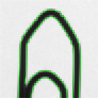
The following images give an example what a displayed match may look when using the transformation matrix in the correct and the erroneous coordinate system, respectively.
For the latter one, shown in image
, the transition matrix is given in pixel-centered coordinates as well and, therefore, the match shown by affine_trans_contour_xld is off by 0.5 pixels.
Note that this effect is only visible when a rotation is involved.
 |
 |
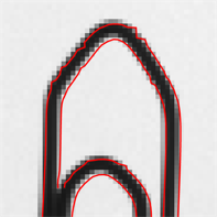 |
Figure 4.
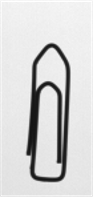
Original image of the paperclip
Part of the match where the inputs are given in the correct coordinates
Match with inputs given in wrong coordinates
Non-Cartesian coordinate systems🔗
- Subpixel-accurate coordinate system – polar coordinates
-
In polar coordinates, points are defined through a distance and an angle. The distance is called the radial coordinate and is given in relation to the fix point, the pole. The angular coordinate is given with respect to a defined axis, the polar axis.
In HALCON, the pole is specified by \((\textrm{Row},\textrm{Column})\), and the polar axis is the horizontal axis. The angular coordinate is given in radians.After a transformation with
polar_trans_image_ext, the upper left pixel in the output image always corresponds to the point in the input image that is specified byRadiusStartandAngleStart. Analogously, the lower right pixel in the output image corresponds to the point in the input image that is specified byRadiusEndandAngleEnd.
In the usual mode (AngleStart<AngleEndandRadiusStart<RadiusEnd), the polar transformation is performed in the mathematically positive orientation (counterclockwise). Further, points with smaller radius lie in the upper part of the output image. By suitably exchanging the values of these parameters (for example,AngleStart>AngleEndorRadiusStart>RadiusEnd), any orientation of the output image can be achieved.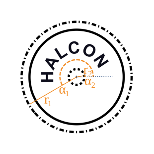
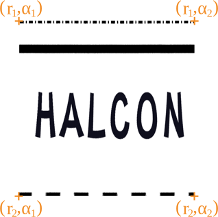
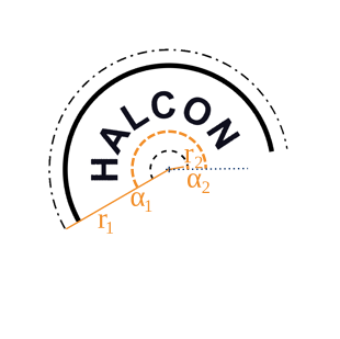
Figure 5. Example showing an annular arc defined by its pole (
Row,Column) (+), the polar axis (…), two angular coordinatesAngleStart(\(\alpha_1\)),AngleEnd(\(\alpha_2\)) and two radial coordinatesRadiusStart(\(r_1\)),RadiusEnd(\(r_2\))
Original image and the parameters defining the annular arc
Annular arc, shown in a figure where the polar coordinates form an equidistant grid obtained bypolar_trans_image_ext
Annular arc in the representation of the original image. The Cartesian coordinates have been obtained throughpolar_trans_image_invon image . The origin is in the center of the pixel in the upper left corner.Polar coordinates are used by the following operators:
Images with a reduced domain, regions, and models🔗
Regarding the origin of the coordinate system used, images with reduced domains, regions, and models are treated differently than other images.
- Images with a reduced domain and regions
- Both images with a reduced domain and regions keep the coordinate system of the image from which they were created. This means that they inherit the origin, and the points keep the coordinate values they had in the original image.
- Models
- Models, on the other hand, can have a local coordinate system.
For example, models obtained via
create_generic_shape_modelhave their origin in the center of gravity of the ROI from which they were created.
Calibrated coordinates🔗
When working with pixel units, it is not possible to extract information about real-world distances directly. When a camera is calibrated, it is possible to rectify the images. In this case, you can assign world coordinates to the image.