3D object model🔗
A 3D object model is a data structure that describes 3D objects. 3D object models can be obtained by several means and they may contain different types of data. Additionally, the different operations that use 3D object models have different requirements concerning the model’s content. Thus, not every operation can be applied to every 3D object model.
Obtaining 3D object models🔗
The following sections give an impression on the various ways that can be used to obtain a 3D object model. Generally, 3D object models can be
-
created from scratch by explicitly setting the coordinates of points lying on the object’s surface or by explicitly setting the parameters of a simple 3D shape,
-
obtained from Computer Aided Design (CAD) data, or
-
derived by one of the available 3D reconstruction approaches.
Obtaining 3D object models from scratch🔗
3D object models can be created from scratch either by using given points that approximate the surfaces of the objects or by using the parameters of simple 3D shapes like boxes, spheres, cylinders, or planes, which are called “3D primitives”. In particular, the following operators are available to create a 3D object model from scratch:
-
gen_empty_object_model_3dcreates an empty 3D object model that can be filled with content, for example, with the operatorset_object_model_3d_attriborset_object_model_3d_attrib_mod, -
gen_object_model_3d_from_pointscreates a 3D object model consisting of points, -
gen_box_object_model_3dcreates a box-shaped 3D primitive, -
gen_sphere_object_model_3dorgen_sphere_object_model_3d_centercreates a sphere-shaped 3D primitive, -
gen_cylinder_object_model_3dcreates a cylinder-shaped 3D primitive, and -
gen_plane_object_model_3dcreates a plane-shaped 3D primitive.
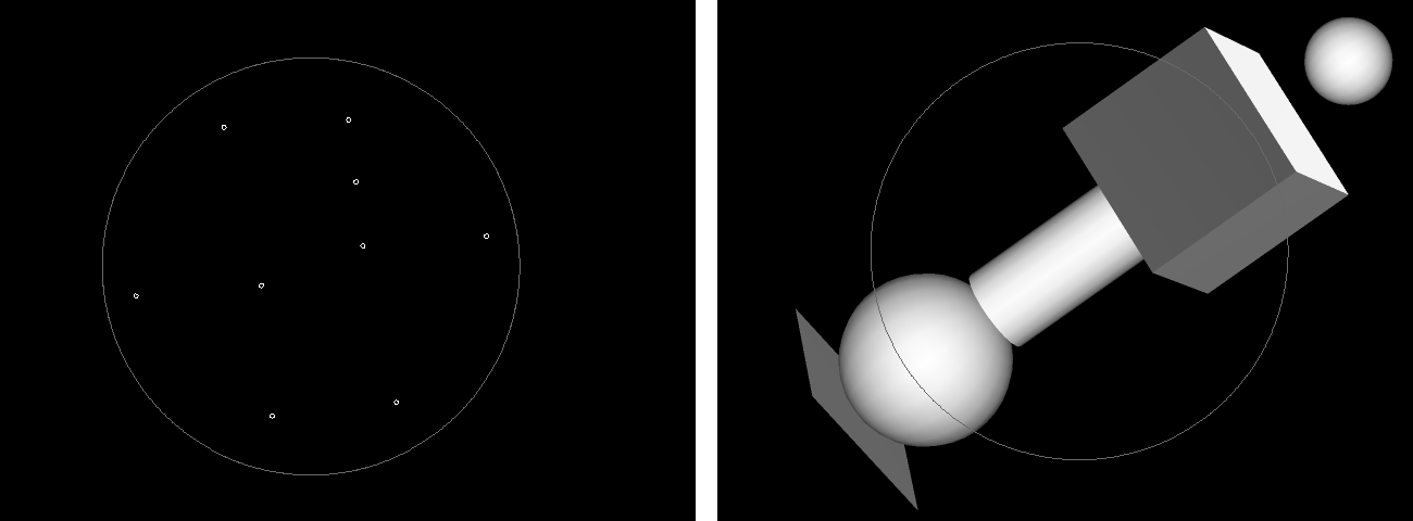
For example, in the HDevelop example program %HALCONEXAMPLES%\hdevelop\3D-Object-Model\Creation\set_object_model_3d_attrib.hdev an empty 3D object model is created with gen_empty_object_model_3d and filled with the point coordinates of a cube using set_object_model_3d_attrib_mod.
The resulting 3D object model, which is a simple point set, is shown in Figure 1 on the left side.
gen_empty_object_model_3d (ObjectModel3D)
PointCoordX := [0.5, 0, 1, 1, 0, 0, 1, 1, 0] - 0.5
PointCoordY := [0, 1, 1, 1, 1, 0, 0, 0, 0] - 0.5
PointCoordZ := [0.5, 0, 0, 1, 1, 0, 0, 1, 1] - 0.5
set_object_model_3d_attrib_mod (ObjectModel3D, ['point_coord_x', 'point_coord_y', 'point_coord_z'], [], [PointCoordX,PointCoordY,PointCoordZ])
In contrast, the HDevelop example program %HALCONEXAMPLES%\hdevelop\3D-Object-Model\Creation\
gen_primitives_object_model_3d.hdev creates different 3D primitives by specifying their parameters.
The resulting 3D object models are displayed in Figure 1 on the right side.
gen_plane_object_model_3d ([0, 0, 0, 0, 0, 0, 0], [], [], ObjectModel3DPlane1)
gen_sphere_object_model_3d ([0, 0, 3, 0, 0, 0, 0], 0.5, ObjectModel3DSphere1)
gen_sphere_object_model_3d_center (-1, 0, 1, 1, ObjectModel3DSphere2)
gen_cylinder_object_model_3d ([1, -1, 2, 0, 0, 60, 0], 0.5, -1, 1, ObjectModel3DCylinder)
gen_box_object_model_3d ([-1, 2, 1, 0, 0, 90, 0], 1, 2, 1, ObjectModel3DBox)
Obtaining 3D object models from CAD data🔗
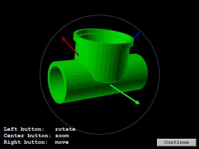
If a 3D model of an object is already available as a Computer Aided Design (CAD) model, for example, as a DXF or PLY file, the model simply can be read as 3D object model with the operator read_object_model_3d as is shown, for example, in the HDevelop example program %HALCONEXAMPLES%\hdevelop\3D-Object-Model\Features\smallest_bounding_box_object_model_3d.hdev (see Figure 2).
Please refer to the description of the operator read_object_model_3d in the Reference Manual for the complete list of supported file formats and their descriptions.
Deriving 3D object models by 3D reconstruction🔗
All (calibrated) 3D reconstruction approaches are suitable to explicitly or implicitly derive a 3D object model. For example, with multi-view stereo you can explicitly obtain a 3D object model, whereas with a common 3D sensor X, Y, and Z images and with depth from focus depth images are obtained.
X, Y, and Z images implicitly contain the information needed for a 3D object model.
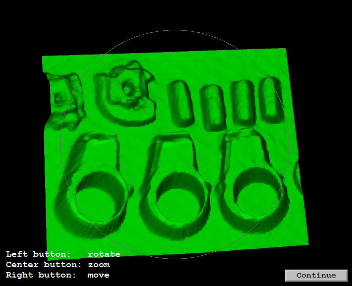
Thus, you can derive a 3D object model from X, Y, and Z images using the operator xyz_to_object_model_3d, as is shown, for example, in the example program %HALCONEXAMPLES%\hdevelop\3D-Object-Model\Features\select_object_model_3d.hdev (see Figure 3).
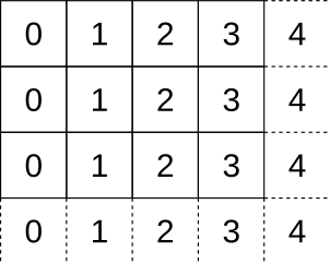
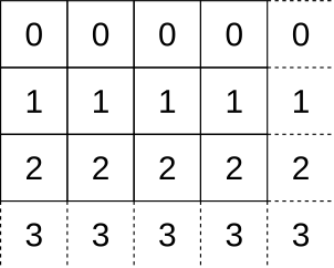
If only a (calibrated) depth image, that is, a “Z image” is available, you can create artificial X and Y images as follows: The X and Y images must have the same size as the Z image. The X image is created by assigning the column numbers of the Z image to each row of the X image and the Y image is created by assigning the row numbers of the Z image to each column of the Y image as is illustrated in a simple (pixel-precise) version in Table 1. The thus created X, Y, and Z images can then be transformed again into a 3D object model. Note that the X and Y images generated in this way usually still need to be multiplied by a suitable factor reflecting the distance between adjacent points in the X and Y directions, respectively, given in units of the Z values.
| X-image | Y-image |
|---|---|
 |
 |
Content of 3D object models🔗
About the information in 3D object models🔗
Because 3D object models can be obtained by several means, the information that is contained in 3D object models differs from model to model.
For example, if a 3D object model is created explicitly from given points using the operator gen_object_model_3d_from_points, the basic information in this model is a set of point coordinates.
In contrast, a model that is created explicitly by the parameters of a 3D primitive contains no points but the parameters of the corresponding simple 3D shape.
Generally, the content of a specific 3D object model depends on the specific process that was used to create or derive it. For example, if a 3D object model is derived from a (calibrated) 3D reconstruction method like stereo vision, sheet of light, or depth from focus, it contains points. If within such a 3D object model a 3D primitives fitting is applied, the model of the resulting 3D primitive contains points as well as the primitive’s parameters. That is, the 3D object model of such a 3D primitive contains more information than that of a 3D primitive that was created explicitly by its parameters.
A 3D object model that is obtained from X, Y, and Z images typically contains the coordinates of the 3D points and the corresponding 2D mapping, that is, a mapping of the 3D points to 2D image coordinates, whereas a 3D object model that is obtained by multi-view stereo can contain a lot of further information.
For example, the surface may be approximated by triangles or polygons.
A triangulation can be applied also explicitly to a 3D object model that contains points using the operator triangulate_object_model_3d.
Different kind of data may be contained in a 3D object model:
-
Points: Coordinates of the 3D points.
If contained in the 3D object model, further parameters can be:
-
Triangles: Indices of the 3D points that represent triangles.
-
Lines: Indices of the 3D points that represent polylines.
-
Faces: Indices of the 3D points that represent faces.
-
Normals: Normal vectors.
-
xyz Mapping: Mapping of a 3D point to image coordinates.
-
-
Primitives.
If contained in the 3D object model, further parameters are:
-
Primitive Type: Type of the primitive (plane, sphere, box, cylinder).
-
Primitive Pose: Pose that describes the position and orientation of the primitive.
-
Primitive Rms: Accuracy of the primitive parameters (only available if they were determined by fitting the primitive into a point cloud).
-
Note that a 3D object model may contain at most one primitive.
-
Extended Attributes.
-
Attribute Names: Names of extended attributes defined for the 3D object model.
-
Attribute Types: Types of extended attributes defined for the 3D object model.
-
-
Additional Attributes.
-
Shape Based Data: Flag that indicates if the 3D object model has been prepared for shape-based 3D matching.
-
Distance Computation: Flag that indicates if the 3D object model has been prepared for distance computation.
-
The content is represented in form of attributes and can be accessed with the operator get_object_model_3d_params.
For the complete list and a detailed description of the available attributes, see the reference manual entry of get_object_model_3d_params.
Querying information from 3D object models🔗
Because many approaches exist to obtain and modify a 3D object model, also many different combinations of information can be contained in the models.
To query the actual content of a specific 3D object model you can apply the operator get_object_model_3d_params.
With this operator, you can query if a specific information, a so-called ‘attribute’, is contained in the model.
For example, you can query if the 3D object model contains primitive data, points, point normals, triangles, faces, or a 2D mapping.
If an attribute is contained in the model, you can query its explicit values with the same operator.
Note that here only the most common attributes were listed.
The complete list of attributes that may be contained in a 3D object model and their descriptions are provided with the operator get_object_model_3d_params.
Modifying 3D object models🔗
Preparing 3D object models for 3D pose recognition🔗
Some 3D position recognition approaches need 3D object models as input.
Especially the shape-based 3D matching and the segmentation that is applied in the context of a 3D primitives fitting need specific information that may be contained only implicitly in the 3D object model.
To prepare a 3D object model for one of these 3D position recognition approaches, that is, to enable a faster internal access to this information, you can use the operator prepare_object_model_3d.
There, for the shape-based 3D matching the parameter Purpose must be set to 'shape_based_matching_3d', whereas for the 3D segmentation it must be set to 'segmentation'.
Note that for a surface-based 3D matching such a preparation is not needed for the actual matching, but may also be required if a visualization with the operator project_object_model_3d using one of the generic parameters 'hidden_surface_removal' or 'min_face_angle' is applied.
Then, similar to the shape-based 3D matching the parameter Purpose of prepare_object_model_3d must be set to 'shape_based_matching_3d'.
Adding attributes to 3D object models🔗
Sometimes, specific attributes are needed, for example, for a following operation, that are not contained explicitly but only implicitly in a 3D object model. Then, different operators are available that can be used to make the implicit information explicit or to manually add or modify specific attributes, for example,
-
set_object_model_3d_attribandset_object_model_3d_attrib_modcan be used to manually add attributes to a 3D object model or to modify the already contained attributes. The main difference between both operators is thatset_object_model_3d_attribreturns a new 3D object model, whereasset_object_model_3d_attrib_modchanges the input 3D object model. Besides standard attributes that can be obtained during the creation or modification of a 3D object model and that are expected by various operators, so-called “extended” attributes can be set, that is, new types of attributes can be defined by the user and attached to a model. These attributes must be indicated in the parameterNameby a preceding “&”. -
surface_normals_object_model_3dcan be used to add the normals attribute to 3D object models. -
triangulate_object_model_3dcan be used to add the triangles attribute to a 3D object model that consists of points and their normals. In particular, the returned 3D object model contains a mesh of triangles that either fits perfectly to the set of points contained in the 3D object model (“greedy” algorithm) or that approximates the set of points (“implicit” algorithm). -
fit_primitives_object_model_3dcan be used to obtain the attributes that are related to 3D primitives. In particular, it can be used to add the parameters of a 3D primitive that fits best into the set of points given in the original 3D object model. Note that such a 3D primitives fitting is often preceded by a segmentation of the 3D object model into different 3D object models having similar characteristics.
How to add attributes using set_object_model_3d_attrib or set_object_model_3d_attrib_mod is shown, for example, in the example program %HALCONEXAMPLES%\hdevelop\3D-Object-Model\Creation\set_object_model_3d_attrib.hdev.
There, the coordinates of the corner points of a cube were added to an empty 3D object model.
Additionally, the attribute for triangles and the corresponding triangle information is added.
Example code: Adding points and triangles to 3D object model
T1 := [0, 8, 5]
T2 := [0, 7, 8]
T3 := [0, 6, 7]
T4 := [0, 5, 6]
T5 := [5, 6, 2]
T6 := [5, 2, 1]
T7 := [6, 7, 3]
T8 := [6, 3, 2]
T9 := [7, 3, 4]
T10 := [7, 4, 8]
T11 := [8, 4, 1]
T12 := [8, 1, 5]
T13 := [2, 3, 4]
T14 := [2, 4, 1]
set_object_model_3d_attrib (ObjectModel3D, 'triangles', [], [T1,T2,T3,T4,T5, T6,T7,T8,T9,T10,T11,T12,T13,T14], ObjectModel3D2)
Note that one of the sides of the cube contains an additional point that is needed to demonstrate how to modify a point coordinate with the operator set_object_model_3d_attrib_mod in a following step (see Table 2).
Thus, this side of the cube is not represented by two but by four triangles.
PointCoordY[0, 3, 6, 7] := [-1, 0.3, -.8, -.3]
set_object_model_3d_attrib_mod (ObjectModel3D2, 'point_coord_y', [], PointCoordY)| 3D object model of a cube | Modification |
|---|---|
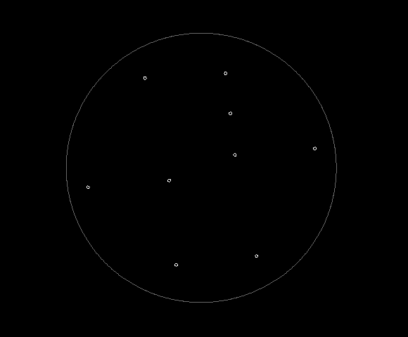 |
Model with point coordinates |
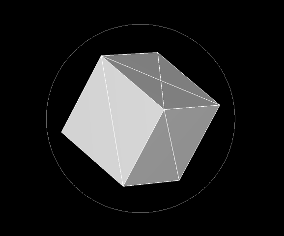 |
Model with added triangles |
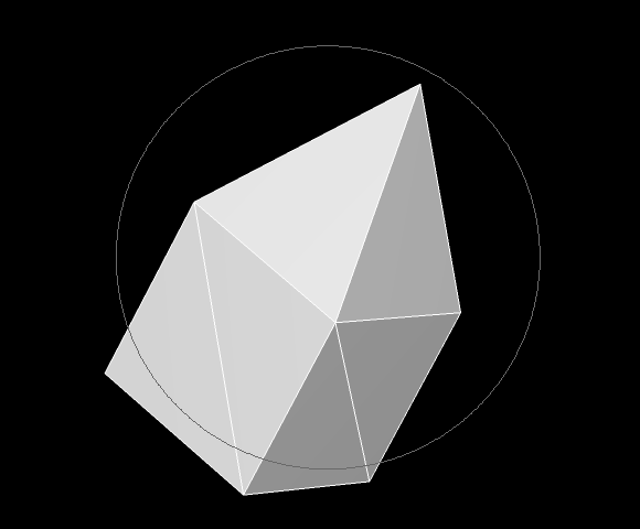 |
Model after modifying a point coordinate |
Removing attributes from 3D object models🔗
To reduce the amount of data stored in a 3D object model, selected attributes of a 3D object model can be removed from the model if they are not needed anymore.
In particular, the operator copy_object_model_3d can be used to copy a 3D object model such that only selected attributes are copied to the new 3D object model.
For example, in the example program %HALCONEXAMPLES%\hdevelop\3D-Object-Model\Segmentation\segment_object_model_3d.hdev a simultaneous segmentation and 3D primitives fitting has been applied to a 3D object model that was obtained from X, Y, and Z images.
To save memory, information like the point coordinates and the 2D mapping, which were obtained automatically during the creation of the 3D object model from the X, Y, and Z images, are removed from the model by copying only the data related to the obtained 3D primitives.
segment_object_model_3d (ObjectModel3DID, [ParSegmentation,ParFitting], [ValSegmentation,ValFitting], ObjectModel3DOutID)
for Index := 0 to |ObjectModel3DOutID| - 1 by 1
  copy_object_model_3d (ObjectModel3DOutID[Index], 'primitives_all', CopiedObjectModel3DID)
endfor
Modifying point sets of 3D object models🔗
Various operators are provided that enable the modification of the 3D object model’s point set or the segmentation of a 3D object model into different parts. For example,
-
set_object_model_3d_attrib_modcan be used to directly modify point coordinates. -
select_points_object_model_3dapplies thresholds to selected attributes to reduce the set of points to those points that lie within the specified attribute value ranges. -
reduce_object_model_3d_by_viewcan be used to reduce the point set to a set of points lying within a specified 2D region that is defined for a specified 2D projection of the 3D object model. -
sample_object_model_3dcan be used to achieve 3D object models with a uniform point density with a specified distance between the points. This is suitable to generally reduce the point density, for example, to enable a faster following operation like a triangulation, or if the 3D object model contains parts for which the point density is higher than for other parts of the object. The latter case may result, for example, from a multi-view stereo reconstruction or from the registration and fusion of multiple 3D object models. Note that, depending on the specified distance between the points, the point density of the resulting 3D object model may even be higher than that of the original one. -
simplify_object_model_3dcan be used to reduce the number of points of triangulated 3D object models, especially for smooth parts of the 3D object model, that is, for parts where a high point density is often not necessary. This may be used, for example, to speed up subsequent operator calls by using the resulting 3D object model with reduced complexity. Typically, the point density of the simplified 3D object model is nonuniform. The point density is higher for parts where more points are required to represent the object’s geometry and it is lower for smoother parts. This is in contrast to the results ofsample_object_model_3d, where a uniform point density is achieved. -
smooth_object_model_3dsmoothens the surface of the 3D object model. Typically, it is used to prepare a 3D object model for a surface triangulation or to smooth noisy point data within a 3D object model. -
segment_object_model_3dsegments a 3D object model into parts with similar characteristics, for example, the same orientation of the normals or a similar curvature. Such a segmentation can be applied, for example, in the context of a 3D primitives fitting. -
connection_object_model_3dsegments a 3D object model into parts that consist of connected components. Whether two components are considered as being connected depends on user-specified criteria, in particular attributes or distance functions and their corresponding threshold values.
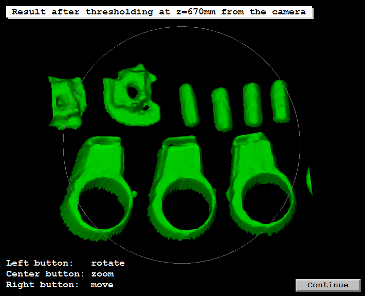
In the example program %HALCONEXAMPLES%\hdevelop\3D-Object-Model\Features\select_object_model_3d.hdev select_points_object_model_3d is used to select points of a 3D object model using a threshold on the z coordinates.
Thus the individual parts of the engine cover shown in
are separated from their background as is shown in
.
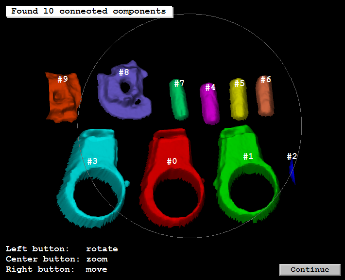
select_points_object_model_3d (ObjectModel3DID, 'point_coord_z', MinValue, MaxValue, ObjectModel3DIDReduced)After excluding the background from the model, the remaining parts are further segmented into connected parts with connection_object_model_3d as is shown in
.
connection_object_model_3d (ObjectModel3DIDReduced, 'distance_3d', 0.010, ObjectModel3DIDConnections)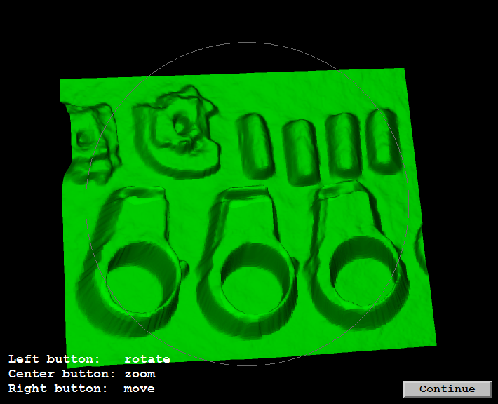 |
 |
 |
|---|---|---|
3D object model in its initial state
3D object model after removing points of the background using a threshold
3D object model after the segmentation into its connected components
Another way to effectively reduce your 3D object model point set for further processing steps is the usage of the 2D mapping of the point data.
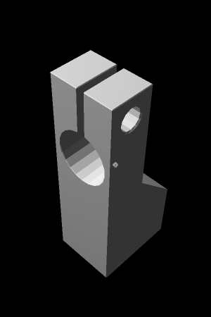
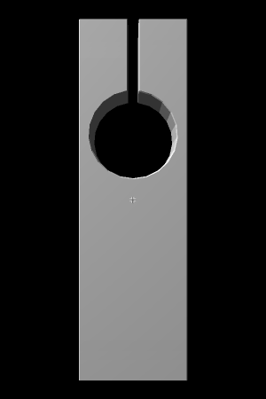
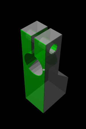
By calling object_model_3d_to_xyz with 'cartesian_faces' set for Type, a 3D object model (which needs to contain polygon or triangle faces) is transformed into the three images X, Y, and Z.
Thereby, the three images solely contain information about those parts of the model, that can be observed by a camera with specified pose and parameters, while hidden parts are omitted (see Table 4).
With xyz_to_object_model_3d you can then perform the reverse transformation and obtain the reduced 3D object model.
 |
 |
 |
|---|---|---|
3D object model in its initial state
3D object model as viewed from the specified camera pose
The resulting object model (green) and the initial model (gray) are visualized together for comparison
In the example program %HALCONEXAMPLES%\hdevelop\3D-Object-Model\Segmentation\reduce_object_model_3d_to_visible_parts.hdev the reduction of an 3D object model using a 2D mapping is shown step by step.
Not just for the reduction of model data, but also for tasks like surface comparison, 2D mappings can be very useful, as by handling 2D images instead of 3D point clouds, significant speed-up can be achieved.
After locating a 3D object model in the observed scene with any alignment method, potential deviations between model and scene can be detected by comparing their respective 2D mappings.
Therefore, use sub_image on the Z images of scene and model, which results in an image, where higher pixel values represent higher deviation between scene and model.
Extract the domain of the defect by applying a suitable threshold.
You can call reduce_object_model_3d_by_view with CamParam set to 'xyz_mapping' in order to reduce your point cloud to the respective view.
In general, the usage of 2D mapping increases speed when handling point clouds. This can for instance be the case when preparing a 3D object model for surface-based matching, for example, by removing outliers, smoothing or reducing its domain.
Especially the operators sample_object_model_3d and surface_normals_object_model_3d benefit, if a 3D object model contains a 2D mapping.
Transforming 3D object models🔗
3D object models can be spatially transformed by several means. In particular, you can transform 3D object models by
-
a rigid 3D transformation using the operator
rigid_trans_object_model_3d, -
an arbitrary affine 3D transformation using the operator
affine_trans_object_model_3d, or -
an arbitrary projective 3D transformation using the operator
projective_trans_object_model_3d.
Note that the transformed 3D object model contains only data that can be represented by a 3D object model and that could be transformed. For example, after an affine 3D transformation no 3D primitives will be contained in the transformed 3D object model. For the transformation of 3D primitives only the rigid transformation is suitable.
Combining 3D object models🔗
To combine several 3D object models to a single 3D object model, you can apply the operator union_object_model_3d.
Note that the resulting model contains only those attributes that are contained in all of the input 3D object models.
Alternatively, you can use fuse_object_model_3d to fuse multiple 3D object models (that are registered in the same coordinate system) into a surface.
See the example %HALCONEXAMPLES%\hdevelop\3D-Object-Model\Transformations\fuse_object_model_3d.hdev to see how to fine-tune the parameters for this operator.
Extracting features of 3D object models🔗
Calculating or accessing features of 3D object models🔗
Several kinds of features are contained explicitly or implicitly in 3D object models.
On the one hand, the 3D object models explicitly contain different attributes.
These attributes can be related to features like point coordinates, normals, triangles, faces, or the parameters of 3D primitives and can be accessed with the operator get_object_model_3d_params.
On the other hand, the 3D object models contain implicit information about specific geometric features, that is, the contained information can be used to explicitly calculate these features using one of the many available operators that are provided by HALCON:
-
area_object_model_3dcalculates the area of the surface of the 3D object model, -
distance_object_model_3dcalculates the distances of the points in one 3D object model to the points, triangles, or primitive in another 3D object model, -
max_diameter_object_model_3dcalculates the maximum diameter of the 3D object model, -
moments_object_model_3dcalculates the mean or the central moment of second order of the 3D object model, -
smallest_bounding_box_object_model_3dandsmallest_sphere_object_model_3dcalculate the smallest bounding box or the smallest sphere surrounding the 3D object model, -
volume_object_model_3d_relative_to_planecalculates the volume of the 3D object model relative to a plane if triangles or a list of polygons is contained in the 3D object model, and -
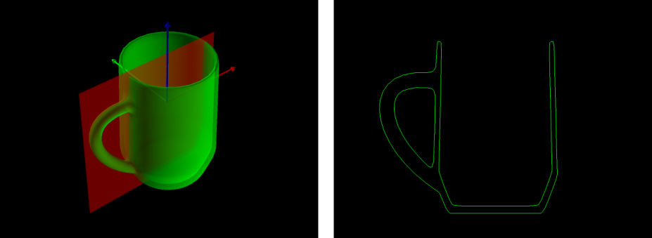
intersect_plane_object_model_3dcalculates an intersection between the 3D object model and a plane and returns the cross section as a set of 3D points that are connected by lines (see, for example, Figure 4, which shows the result of the example program%HALCONEXAMPLES%\hdevelop\3D-Object-Model\Transformations\intersect_plane_object_model_3d.hdev).
In the example program %HALCONEXAMPLES%\hdevelop\3D-Object-Model\Features\select_object_model_3d.hdev the maximum diameters and the volumes for the connected components of the 3D object model are calculated (see Table 5).
volume_object_model_3d_relative_to_plane (ObjectModel3DIDConnections, [0, 0, MaxValue,0, 0, 0, 0], 'signed', 'true', Volume)
max_diameter_object_model_3d (ObjectModel3DIDConnections, Diameter)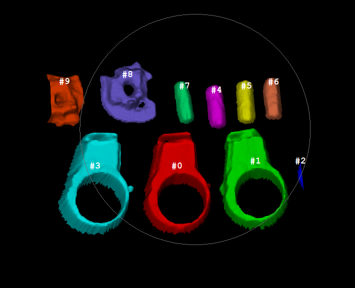
| # | Max. diameter | Volume |
|---|---|---|
| 0 | 187.1 mm | 0.400 dm² |
| 1 | 187.5 mm | 0.375 dm² |
| 2 | 55.5 mm | 0.002 dm² |
| 3 | 187.7 mm | 0.408 dm² |
| 4 | 86.0 mm | 0.041 dm² |
| 5 | 85.2 mm | 0.043 dm² |
| 6 | 85.6 mm | 0.042 dm² |
| 7 | 84.2 mm | 0.036 dm² |
| 8 | 129.4 mm | 0.125 dm² |
| 9 | 112.0 mm | 0.107 dm² |
Selecting 3D object models by their features🔗
If many 3D object models are available but only those 3D object models are needed that have specific features, the operator select_object_model_3d can be applied.
It selects 3D object models from an array of 3D object models according to global features like the existence of specific attributes or specific value ranges for features like the object’s mean diameter or the object’s volume.
For example, in the example program %HALCONEXAMPLES%\hdevelop\3D-Object-Model\Features\select_object_model_3d.hdev the maximum diameter and the volume of the connected components of the 3D object model are used to select only those components that have a certain size.
The selected models are visualized in Figure 5.
select_object_model_3d (ObjectModel3DTranslated, ['volume', 'diameter_object'], 'and', [MinVolume,MinDiameter], [MaxVolume,MaxDiameter], ObjectModel3DSelected)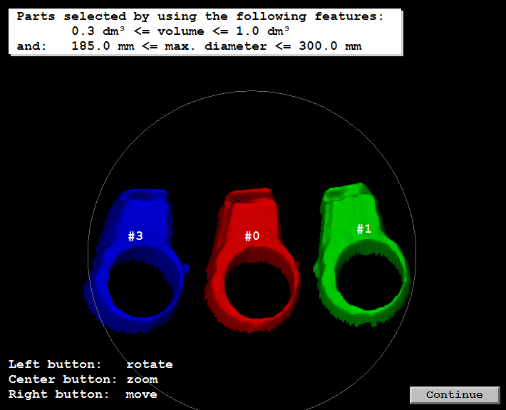
Registering 3D object models🔗
HALCON provides functionality for matching 3D object models that represent the same object or overlapping parts of the same object. This matching is also called “registration” of 3D object models.
With the operator register_object_model_3d_pair you can apply a matching between two 3D object models to get the pose that describes the spatial relation between them.
This process is also called “pair-wise registration” of 3D object models.
The matching determines an initial pose that is then consecutively refined so that the mutual difference between the overlapping parts of both 3D object models becomes minimal.
The final pose can be used to transform the first 3D object model into the coordinate system of the second 3D object model.
Note that if both models are already available in the same coordinate system, the initial pose between them is already implicitly known.
Then, the operator can also be applied in a mode that performs no initial matching but only the pose refinement (Method='icp').
With the operator register_object_model_3d_global you can improve the relative positions between many 3D object models, which is also called “global registration” of 3D object models.
In particular, if a 3D object consists of several overlapping 3D object models, the specific overlaps are used to determine an array of homogeneous transformation matrices with which the models can be transformed such that the relation between all models is refined, that is, a minimal mutual difference between all 3D object models is realized, which leads to a better representation of the complete object.
For both operators, the result of the registration is typically used to transform the initial 3D object models with the operator affine_trans_object_model_3d.
See the example program %HALCONEXAMPLES%\hdevelop\Applications\Robot-Vision\reconstruct_3d_object_model_for_matching.hdev for an example application.
Visualizing 3D object models🔗
For the visualization of 3D object models, different operators and procedures are available.
-
Visualization of individual 3D object models with
disp_object_model_3d.-
Visualization of individual 3D object models without the need to set camera parameters and pose.
-
disp_object_model_3dprovides an easy to use interface for the visualization of one or a small number of 3D object models.
See the example program
disp_object_model_3d.hdevfor a demonstration of the visualization options usingdisp_object_model_3d. -
-
Visualization of multiple 3D object models, a so called ‘3D scene’, with
display_scene_3d.-
Best choice if multiple 3D object models should be displayed.
-
Multiple cameras can be defined to view the 3D scene from different positions.
-
Labels can be attached to specific 3D points.
-
Smooth display of dynamic scenes since the handle can manage the caching of the objects on the graphics card.
See the example program
display_scene_3d.hdevfor a demonstration of the visualization options usingdisp_scene_3d. -
-
Interactive visualization of 3D object models with the procedure
visualize_object_model_3d.- Visualization of 3D object models with the possibility to interactively change their position and orientation.
Note that the visualization of 3D object models requires OpenGL 2.1, GLSL 1.2, and the OpenGL extensions GL_EXT_framebuffer_object and GL_EXT_framebuffer_blit. If these requirements are not fulfilled, for example, because of the use of Windows Remote Desktop or SSH forwarding, a compatibility mode with less requirements but lower quality is automatically enabled.