Descriptor-based matching🔗
General concept🔗
Similar to the perspective deformable matching, the descriptor-based matching is able to find objects even if they are perspectively deformed. Again, the matching can be applied either for a calibrated camera or for an uncalibrated camera. In contrast to the perspective deformable matching, the template is not built by the shapes of contours but by a set of so-called interest points. These points are first extracted by a detector and then are described, that is, classified according to their location and their local gray value neighborhood, by a descriptor.
A first example🔗
In this section we give a quick overview of the matching process with (calibrated) descriptor-based matching.
To follow the example actively, start the HDevelop program %HALCONEXAMPLES%\hdevelop\Applications\Object-Recognition-2D\locate_cookie_box.hdev, which locates a cookie box label that is aligned in different directions.
Step 1: Select the object in the reference image
First, the reference image is read and the image is reduced to a rectangular ROI. That is, a template image is derived that contains only the label of one specific side of a cookie box.
read_image (Image, 'packaging/cookie_box_01')
gen_rectangle1 (Rectangle, 224, 115, 406, 540)
reduce_domain (Image, Rectangle, ImageReduced)
As a calibrated matching is performed, the camera parameters and the reference pose of the label relative to the camera are needed. For a precise matching, these should be obtained, for example, by a camera calibration. In the example, the pose is obtained by corresponding points, in particular by the image coordinates and the estimated world coordinates of the corner points of the rectangle from which the ROI was created.
Step 2: Create the model
The camera parameters and the reference pose are input to create_calib_descriptor_model, which is applied to create the calibrated descriptor model.
Within the operator, the detector is selected and parameters for the detector as well as for the descriptor are specified.
In this case, the parameters for the detector are specified with [], that is, the default values are selected.
To be able to reuse the created descriptor model, it is stored to file with write_descriptor_model.
create_calib_descriptor_model (ImageReduced, CamParam, Pose, 'harris_binomial', [], [], ['depth', 'number_ferns', 'patch_size', 'min_scale', 'max_scale'], [11, 30, 17, 0.4, 1.2], 42, ModelID)
write_descriptor_model (ModelID, 'cookie_box_model.dsm')
Step 3: Find the object again
find_calib_descriptor_model now locates the cookie box label in the search images.
The returned 3D poses describe the relation between the world coordinates of the model and the world coordinates of the found matches.
Figure 1 shows a search image with the visualized result.
for Index := 1 to 10 by 1
    read_image (Image, 'packaging/cookie_box_' + Index$'.02')
    find_calib_descriptor_model (Image, ModelID, [], [], [], [], 0.25, 1, CamParam, 'num_points', Pose, Score)
endfor
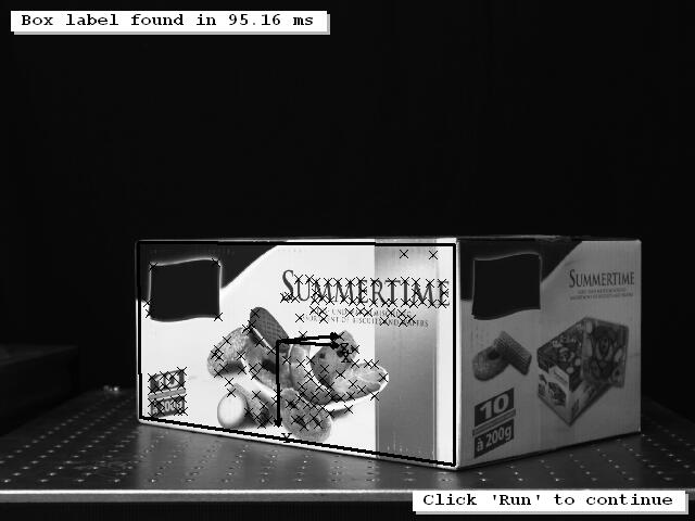
Step 4: Visualize the match
The result is visualized by different means.
First, the interest points of the found model instance are queried with get_descriptor_model_points and can be immediately displayed as crosses using gen_cross_contour_xld.
get_descriptor_model_points (ModelID, 'search', 0, Row, Col)
gen_cross_contour_xld (Cross1, Row, Col, 6, 0.785398)
Then, the 3D coordinate system of the 3D pose is visualized by the procedure disp_3d_coord_system.
Finally, the rectangle that presents the outline of the cookie box label is displayed. For that, the rectangle must pass through different transformation steps. In particular, a transformation from the reference image to the world coordinate system (WCS) is followed by a 3D affine transformation within the WCS, which is followed by a transformation from the WCS to the search image.
As regions in HALCON cannot be transformed by a 3D transformation, the corner points of the rectangle must be transformed instead.
Here, the world coordinates of the rectangle’s corner points are obtained with image_points_to_world_plane.
To apply the following 3D affine transformation with affine_trans_point_3d, the 3D pose that was returned by the matching must be converted into a 3D homogeneous transformation matrix using pose_to_hom_mat3d.
pose_to_hom_mat3d (Pose, HomMat3D)
affine_trans_point_3d (HomMat3D, XOuterBox, YOuterBox, [0, 0, 0, 0], XTrans, YTrans, ZTrans)
The 3D coordinates obtained by the 3D affine transformation are then projected with project_3d_point into the search image, so that the rectangle can be reconstructed and displayed.