Local deformable matching🔗
General concept🔗
Like shape-based matching, local deformable matching extracts contours and matches their shapes against the shapes of previously created models.
But in contrast to shape-based matching, slightly deformed contours are not only found but the deformations are returned as result. Note that the actual location of the object is restricted to determining its position, whereas the orientation and scale are interpreted as part of the deformation.
A first example🔗
In this section we give a quick overview of the matching process with local deformable matching.
To follow the example actively, start the example program %HALCONEXAMPLES%\hdevelop\Matching\Deformable\find_local_deformable_model.hdev, which locates differently deformed “MVTec” logos (see Figure 1)

Step 1: Prepare the template
First, the template is prepared.
In particular, the procedure create_mvtec_logo_broadened extracts the “MVTec” logo from an image and creates a synthetic image with a slightly broader logo.
The obtained colored image (Figure 1, left) is transformed into a gray value image from which an ROI, that is, the template image is derived (see
).
create_mvtec_logo_broadened (LogoImage, 0, 200, Width, Height)
rgb1_to_gray (LogoImage, GrayImage)
gen_rectangle1 (Rectangle, 82, 17, 177, 235)
reduce_domain (GrayImage, Rectangle, ImageReduced)
Step 2: Create the model
The template image is then used to create a model of the logo using create_local_deformable_model. The contours of the model can be queried with get_deformable_model_contours, for example, to overlay a later match by it to visually inspect the deformations (see Figure 1, right).
create_local_deformable_model (ImageReduced, 'auto', [], [], 'auto', 1, [], 'auto', 1, [], 'auto', 'none', 'use_polarity', 'auto', 'auto', [], [], ModelID)
get_deformable_model_contours (ModelContours, ModelID, 1)
Step 3: Find the object again
The created model is used to find instances of the logo in search images.
For demonstration purposes, the example uses synthetic search images that show the logo with various random deformations.
After transforming the colored images again into the corresponding gray value images (see, for example,
, middle), the matching is applied with find_local_deformable_model.
 |
 |
 |
|---|---|---|
template image
corresponding part of the search image
rectified image
rgb1_to_gray (SearchImage, GrayImage)
find_local_deformable_model (GrayImage, ImageRectified, VectorField, DeformedContours, ModelID, 0, 0, 1, 1, 1, 1, 0.5, 1, 1, 4, 0.9, ['image_rectified', 'vector_field', 'deformed_contours'], ['deformation_smoothness', 'expand_border', 'subpixel'], [Smoothness,0, 1], Score, Row, Column)
By default, the operator returns the position of the object in the image.
With the parameter ResultType, you can additionally specify some iconic objects that are returned.
In the example program, all available iconic objects – that is, a rectified version of the part of the search image that corresponds to the bounding box of the ROI that was used to create the model (see
, right), the vector field that describes the deformations of the matched model instance, and the contours of the deformed model instance – are queried.
Step 4: Visualize the deformations
To visualize the deformations of a found model instance, the procedure gen_warped_mesh creates a regular grid and deforms it with the information that is contained in the returned vector field.
For that, the vector field is first converted into the two real-valued images DRow and DCol using vector_field_to_real.
For each point of the model, or more precisely of the bounding box that surrounds the template image, DRow contains the corresponding row coordinates and DCol the corresponding column coordinates of the search image.
Then, a regular grid with the size of the model is created.
The horizontal and vertical grid lines are created in separate loops using the operators tuple_gen_sequence and tuple_gen_const.
Using the images DRow and DCol, for each point of a grid line get_grayval_interpolated queries the corresponding “deformed” point, that is, the corresponding coordinates of the point in the search image.
These coordinates are used to create polygons that represent the deformed horizontal and vertical grid lines.
Mesh generation code
procedure gen_warped_mesh (VectorField, WarpedMesh, Step)
gen_empty_obj (WarpedMesh)
count_obj (VectorField, Number)
for Index := 1 to Number by 1
    select_obj (VectorField, ObjectSelected, Index)
    vector_field_to_real (ObjectSelected, DRow, DCol)
    get_image_size (VectorField, Width, Height)
    for ContR := 0.5 to Height[0] - 1 by Step
        Col1 := [0.5:Width[0] - 1]
        tuple_gen_const (Width[0] - 1, ContR, Row1)
        get_grayval_interpolated (DRow, Row1, Col1, 'bilinear', GrayRow)
        get_grayval_interpolated (DCol, Row1, Col1, 'bilinear', GrayCol)
        gen_contour_polygon_xld (Contour, GrayRow, GrayCol)
        concat_obj (WarpedMesh, Contour, WarpedMesh)
    endfor
    for ContC := 0.5 to Width[0] - 1 by Step
        Row1 := [0.5:Height[0] - 1]
        tuple_gen_const (Height[0] - 1, ContC, Col1)
        get_grayval_interpolated (DRow, Row1, Col1, 'bilinear', GrayRow)
        get_grayval_interpolated (DCol, Row1, Col1, 'bilinear', GrayCol)
        gen_contour_polygon_xld (Contour, GrayRow, GrayCol)
        concat_obj (WarpedMesh, Contour, WarpedMesh)
    endfor
endfor
return ()
The grid is displayed together with the returned contours of the deformed logo as shown in Figure 2.
dev_display (SearchImage)
dev_display (WarpedMesh)
dev_display (DeformedContours)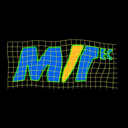
The difference between the returned rectified image and the template image is visualized as shown in Figure 3.
crop_domain (ImageReduced, ImagePart)
abs_diff_image (ImagePart, ImageRectified, ImageAbsDiff1, 1)
dev_display (ImageAbsDiff1)