Workflow🔗
Selecting the model ROI🔗
As a first step of the shape-based matching, the region of interest that specifies the template image must be selected. This region can have an arbitrary shape, that is, it can also contain holes or consist of several parts that are not connected. Thus, it is possible to create an ROI that contains only “robust” parts of the object. The ROI must be selected so that it contains all prominent structures of the object and also some pixels outside of them, as their immediate surroundings (neighborhood) are needed to derive the model.
You can speed up the later search using a subsampling. For that, the ROI should not be too “thin”, because otherwise it vanishes at higher pyramid levels! As a rule of thumb, you are on the safe side if an ROI is \(2^{NumLevels−1}\) pixels wide. That is, a width of 8 pixels allows to use 4 pyramid levels. After having selected a suitable ROI, the reduced image is used as template image for the creation of the model.
When using shape-based matching in the presence of clutter in the reference image, you can also use the operator inspect_shape_model to improve an interactively selected ROI by additional image processing.
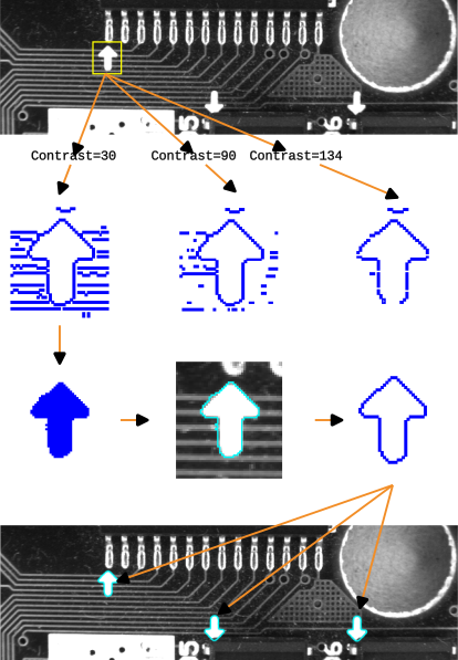
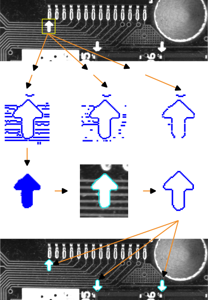
This is shown in the HDevelop example program %HALCONEXAMPLES%\solution_guide\matching\process_shape_model.hdev, which locates the arrows that are shown in Figure 1.
inspect_shape_model.
Interactive ROI,
models for different values of Contrast,
(left to right) processed model region, final ROI, final model,
result of the search
Step 1: Select the arrow
There, an initial ROI is created around the arrow, without trying to exclude clutter .
gen_rectangle1 (ROI, 361, 131, 406, 171)
reduce_domain (ModelImage, ROI, ImageROI)
Step 2: Create a first model region
Then, this ROI is inspected via inspect_shape_model.
inspect_shape_model (ImageROI, ShapeModelImage, ShapeModelRegion, 1, 30)
shows the shape model regions that would be created for different values of the parameter Contrast.
As you can see, you cannot remove the clutter without losing characteristic points of the arrow itself.
Step 3: Process the model region
This problem can be solved by exploiting the fact that the operator inspect_shape_model returns the shape model region.
Thus, you can process it like any other region.
The main idea to get rid of the clutter is to use the morphological operator opening_circle, which eliminates small regions.
Before this, the operator fill_up must be called to fill the inner part of the arrow, because only the boundary points are part of the (original) model region.
fill_up (ShapeModelRegion, FilledModelRegion)
opening_circle (FilledModelRegion, ROI, 3.5)
Step 4: Create the final model
The obtained region is then used to create the model for a matching that locates all arrows successfully. shows the processed region, the corresponding region of interest, and the final model region.
reduce_domain (ModelImage, ROI, ImageROI)
create_generic_shape_model (ModelID)
train_generic_shape_model (ImageROI, ModelID)
Creating suitable shape models🔗
Having derived the template image from the reference image, the shape model can be trained.
Before the training, an empty shape model needs to be created using create_generic_shape_model and possibly configured.
Parameters modifying the model itself need to be set before the training.
Let HALCON assist you
-
Use automatic parameter suggestion:
For many parameters you can let HALCON suggest suitable parameters. Then, you can either leave'auto'as the corresponding parameter value (default value for the parameters where HALCON can automatically determine value suggestions, seeset_generic_shape_model_param), or you applydetermine_shape_model_paramsto automatically determine parameters for a shape model from a template image and then decide individually if you set the suggested values for the shape model. Note that both approaches return only approximately the same values andtrain_generic_shape_modelandfind_generic_shape_model, respectively, return the more precise values. -
Inspect the model:
HALCON offers different options to inspect the model and check automatically set parameters
Specifying pixels that are part of the model🔗
Affected parameters
'contrast_high', 'contrast_low', 'min_size'
The shape of the object needs to be extracted without possible clutter. This is done by:
- Selecting all those points whose neighboring contrast exceeds a certain threshold.
- Rejecting components smaller than the minimum number of points.
Alternative methods to remove clutter are to modify the ROI or create a synthetic model.
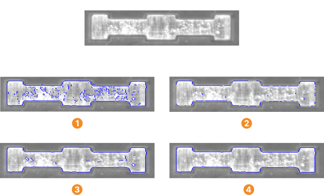
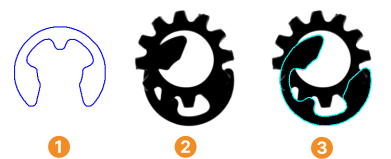
Figure 2 shows an example. The task is to create a model for the outline of the pad. If the complete outline is selected, the model also contains clutter ( ). If the clutter is removed, parts of the outline are missing .
set_generic_shape_model_param.
complete object containing clutter: 'contrast_low' = 'contrast_high' = 40,
little clutter but incomplete object: 'contrast_low' = 'contrast_high' = 70,
hysteresis threshold: 'contrast_low' = 40, 'contrast_high' = 70,
minimum contour size: 'contrast_low' = 'contrast_high' = 40 and 'min_size' = 30
Tip
You can let HALCON select suitable values itself by specifying the value 'auto' for the respective parameters.
But it is recommended to verify them using inspect_shape_model before training the model.
- Setting the required model contrast-parameters:
-
For the model those pixels are selected, whose contrast, that is, gray value difference to neighboring pixels, exceeds a threshold. In order to obtain a suitable model the contrast should be chosen in such a way that the significant pixels of the object are included, that is, those pixels that characterize it and allow to discriminate it clearly from other objects or from the background. Obviously, the model should not contain clutter, that is, structures that do not belong to the object.
The threshold can be specified as a single value or as a hysteresis threshold, depending on the values for
'contrast_low'and'contrast_high', which can be set usingset_generic_shape_model_param.A hysteresis threshold is useful in cases where it is impossible to find a single threshold value that removes all the clutter but not also parts of the object. It uses two thresholds, a lower and an upper threshold (see also the operator hysteresis_threshold). For the model, first pixels that have a contrast higher than the upper threshold are selected. Then, pixels that have a contrast higher than the lower threshold and that are connected to a high-contrast pixel, either directly or via another pixel with contrast above the lower threshold, are added.
This method enables you to select contour parts whose contrast is locally low. Returning to the example with the pad: As you can see in , with a hysteresis threshold you can create a model for the complete outline of the pad without clutter.
The following line of code shows how to inspect the two thresholds (note, operator
inspect_shape_modeluses a different syntax):inspect_shape_model (ImageReduced, ModelImages, ModelRegions, 2, [40,70])Note also, the parameter
'contrast_low'and'contrast_high'are for the model. The minimal contrast a point must at least have in a search image in order to be compared with the model is determined by'min_contrast'. - Setting a minimum model size using
'min_size': -
An other possibility to remove clutter is to specify a minimum size, that is, number of pixels, for the contour components. shows the result for the example task. The minimum size is set through
'min_size'usingset_generic_shape_model_param. The following line of code shows how to inspect the minimum size (note, operatorinspect_shape_modeluses a different syntax):inspect_shape_model (ImageReduced, ModelImages, ModelRegions, 2, [40,40,30])
Speeding up the search using subsampling and point reduction🔗
Affected parameters
'num_levels', 'optimization'
The search can be sped up by reducing the number of points to examine. This can be achieved by - reducing the number of image points via subsampling, - reducing the number of model points via model optimization.
- Subsampling:
-
Subsampling can be used to speed up the search. An image pyramid is created, consisting of the original, full-sized image and a set of downsampled images. The model is then trained to search on the different pyramid levels.
You can specify how many pyramid levels are used via the parameter
'num_levels'usingset_generic_shape_model_param. We recommend to choose the highest pyramid level at which the model contains at least 10-15 pixels and in which the shape of the model still resembles the shape of the object.Tip
You can let HALCON select a suitable value itself by specifying the value
'auto'for'num_levels'.You can then query the used value via the operator
get_generic_shape_model_param.Note
If you want to set the number of pyramid levels manually, you can inspect the template image pyramid using the operator
inspect_shape_model, for example, as shown in the example program%HALCONEXAMPLES%\solution_guide\matching\first_example_shape_matching.hdev.After the call to
inspect_shape_model, the model regions on the selected pyramid levels are displayed in the graphics window.The code lines following the operator call loop through the pyramid and determine the highest level on which the model contains at least 15 points. This value is then used in the call to the operator
train_generic_shape_model.inspect_shape_model (ModelImage, ShapeModelImages, ShapeModelRegions, 8, 30) area_center (ShapeModelRegions, AreaModelRegions, RowModelRegions, ColumnModelRegions) * Possible way to determine the model levels. count_obj (ShapeModelRegions, HeightPyramid) for i := 1 to HeightPyramid by 1 if (AreaModelRegions[i - 1] >= 15) NumLevels := i endif endfor create_generic_shape_model (ModelID) set_generic_shape_model_param (ModelID, 'num_levels', NumLevels) train_generic_shape_model (ModelImage, ModelID)Note that the operator
inspect_shape_modelreturns the pyramid images in form of an image tuple (array). The individual images can be accessed like the model regions with the operatorselect_obj.Note
Object tuples start with the index 1, whereas control parameter tuples start with the index 0!
- Model optimization:
-
A further reduction of model points can be enforced via the parameter
'optimization'usingset_generic_shape_model_param. This may be useful to speed up the matching in the case of particularly large models. Again, we recommend to specify the value'auto'to let HALCON select a suitable value itself.Note
Regardless of your selection all points passing the contrast criterion are displayed, that is, you cannot check which points are part of the model.
Allowing a range of scale🔗
Affected parameters
'iso_scale_max', 'iso_scale_min', 'iso_scale_step', 'scale_column_max', 'scale_column_min', 'scale_column_step', 'scale_row_max', 'scale_row_min', 'scale_row_step'
You can specify an allowed range of scale. To do so, two forms are on hand:
- Isotropic scaling:
-
Identical scaling in row and column direction (uniform scaling). To do so, you specify the smallest and largest allowed scaling value as well as the step length between two sampled points in order to determine the granularity of the scaling.
See also
set_generic_shape_model_param. - Anisotropic scaling:
-
Different scaling in row and column direction. To do so, you also specify the smallest and largest allowed scaling value as well as the step length between two sampled points in order to determine the granularity of the scaling. But in case of anisotropic scaling you specify these values for the row and column direction independently.
See also
set_generic_shape_model_param.
You can further limit the allowed range during the search. Thus, if you want to reuse a model for different tasks requiring a different range of scale, you can use a large range when creating the model and a smaller range for the search.
Note
If you are searching for the object on a large range of scales you should create the model based on a large scale because HALCON cannot “guess” model points when precomputing model instances at scales larger than the original one. On the other hand, the image pyramid should be created such that the highest level contains enough model points also for the smallest scale.
Details about 'auto' step size
If you select the value 'auto' for the step parameters 'iso_scale_step' and its anisotropic equivalents, HALCON automatically chooses a suitable step size to obtain the highest possible accuracy by determining the smallest scale change that is still discernible in the image.
A scaled object is clearly discernible from the original if the point that lies farthest from the center of the object is moved by at least 2 pixels. Therefore, the corresponding scale change \(\Delta s_{opt}\) is calculated as follows:
with \(l\) being the maximum distance between the center and the object boundary and \(d = 2\) pixels. For some models, the such estimated scale step size is still too large. In these cases, it is divided by 2 automatically.
The automatically determined scale step size is suitable for most applications.
Therefore, we recommend to select the value 'auto'.
By selecting a higher value you can speed up the search process, however, at the cost of a decreased accuracy of the estimated scale.
Note that for very high values the matching may fail altogether!
The value chosen for the step parameters should not deviate too much from the optimal value (\(\frac{1}{3}\Delta s_{opt} \leq \Delta s \leq 3\Delta s_{opt}\)).
Note that choosing a very small step size does not result in an increased scale accuracy!
Modifying the angle sampling🔗
Affected parameter
'angle_step'
During the matching process, the model is searched for in different angles within the allowed range, at steps specified with the parameter 'angle_step'. Thus, for orientation angles
with \(n\) being an integer. In this section we will have a look at possible values for 'angle_step'.
If you select the value 'auto', HALCON automatically chooses an optimal step size \(\Phi_{opt}\) to obtain the highest possible accuracy by determining the smallest rotation that is still discernible in the image.
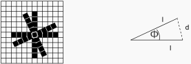
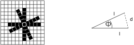
The underlying algorithm is explained in Figure 3: The rotated version of the cross-shaped object is clearly discernible from the original if the point that lies farthest from the center of the object is moved by at least 2 pixels. Therefore, the corresponding angle \(\Phi_{opt}\) is calculated as follows:
with \(l\) being the maximum distance between the center and the object boundary and \(d = 2\) pixels. For some models, the angle step size estimated this way is too large. In these cases, it is divided by 2 automatically.
The automatically determined angle step size \(\Phi_{opt}\) is suitable for most applications.
Therefore, we recommend to select the value 'auto'.
You can query the used value after the creation via the operator get_generic_shape_model_param.
By selecting a higher value you can speed up the search process, however, at the cost of a decreased accuracy of the estimated orientation.
Note that for very high values the matching may fail altogether!
The value chosen for 'angle_step' should not deviate too much from the optimal value (\(\frac{1}{3}\Phi_{opt} \leq \Phi \leq 3\Phi_{opt}\)).
Note that choosing a very small step size does not result in an increased angle accuracy!
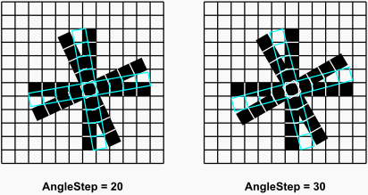
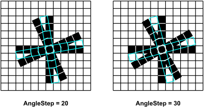
If the value for the parameter 'angle_step' is significantly larger than the automatically selected minimum value, the effect depicted in Figure 4 can occur:
If the object lies between two precomputed angles, points lying far from the center are not matched to a model point, and therefore the score decreases.
'angle_step' on the matching. Specifying how pixels are compared with the model🔗
Affected parameter
'metric'
Polarity, that is, the direction of the contrast, can vary between different images.
You can specify whether and how the polarity must be observed (see Table 1) using the parameter 'metric'.
Different ways to handle the polarity and thus different values for 'metric':
'use_polarity':- The polarity is observed, that is, the points in the search image must show the same direction of the contrast as the corresponding points in the model. If, for example, the model is a bright object on a dark background, the object is found in the search images only if it is also brighter than the background.
'ignore_global_polarity':- The polarity is globally ignored. In this mode, an object is recognized also if the direction of its contrast reverses, for example, if your object can appear both as a dark shape on a light background and vice versa. This flexibility, however, is obtained at the cost of a slightly lower recognition speed.
'ignore_local_polarity':- The object is found even if the contrast changes locally. This mode can be useful, for example, if the object consists of a part with a medium gray value, within which either darker or brighter subobjects lie. Please note however, that the recognition speed and the robustness may decrease dramatically in this mode, especially if you allowed a large range of rotation.
'ignore_color_polarity':- You can perform the matching in color images (or, more generally, in multi-channel images).
An example is
%HALCONEXAMPLES%\hdevelop\Applications\Position-Recognition-2D\matching_multi_channel_yogurt.hdev.
| Template image |  |
|
|
|---|---|---|---|
| Search images | |
 |
 |
found using 'use_polarity' |
 |
 |
|
found using 'ignore_global_polarity' |
|
|
|
found using 'ignore_local_polarity' |
|
|
|
Model from XLD
If you train your model with XLD contours, there is no information about the polarity of the model available.
Thus, for such a model the value of 'metric' must be set to 'ignore_local_polarity'.
You can change this setting after a first successful matching.
With get_generic_shape_model_result you can retrieve the transformation matrix to project the contour onto the search image.
Then, with the operator set_shape_model_metric you can determine the polarity of the first search image, which is used as training image for the polarity, and set the match metric to 'use_polarity' or 'ignore_global_polarity'.
Using the value 'use_polarity', that is, if the following search images have the same polarity as the training image, the search becomes faster and more robust.
An example is %HALCONEXAMPLES%\hdevelop\Matching\Shape-Based\create_shape_model_xld.hdev.
Note that set_shape_model_metric is only available for models that are created from XLD contours!
Using sample-based training🔗
Fine-tuning model parameters and contours can be challenging, as many factors need to be taken into account simultaneously.
Sample-based training can be used to automatically estimate parameter values and optimize model contours according to the match instances provided in those samples.
The parameter that controls sample-based training is 'sample_based_training'.
See the example programs %HALCONEXAMPLES%\hdevelop\Matching\Shape-Based\train_generic_shape_model_sample_workflow.hdev or %HALCONEXAMPLES%\hdevelop\Matching\Shape-Based\train_generic_shape_model_contour_pruning_workflow.hdev for workflows using sample-based training.
Setting samples🔗
The samples need to be provided as a tuple of dictionaries, each containing both an image and one or multiple ROIs defining the respective ground-truth of instances of the object to be searched for.
They are then added to the shape model using set_generic_shape_model_param with the parameter 'training_samples'.
TrainingSamples[0] := dict{image: SampleImage1, region: SampleImage1Labels}
TrainingSamples[1] := dict{image: SampleImage2, region: SampleImage2Labels}
set_generic_shape_model_param (ModelID, 'training_samples', TrainingSamples)
The sample-based training highly depends on the selection of sample images and the respective sample regions, therefore the following criteria should be considered when choosing a set of samples:
- Representation
- The samples need to be representative of all instances that can occur in the search process. For example, if objects can be occluded in the search images, this should be reflected in the sample images as well.
- Number of samples
- The ideal number of samples depends on the variety of object instances that should be detected. Most cases are sufficiently covered by providing about 10 samples.
- Sample distribution
- Especially for the contour optimization, the distribution of sample variations must also be representative. If unstable model parts are overrepresented in the samples, an unexpectedly high threshold is needed to prune them.
- Sample region
- The sample region must contain the complete model instance, meaning all contours of the complete unmodified model instance have to be inside the sample region.
In case sample-based training is used to modify the model, the unmodified model region can be determined using
inspect_shape_model. - Model reference point
- The sample region must contain the model reference point of the match instance to be found.
After the samples are set, (re-)training the shape model with train_generic_shape_model adapts the shape model according to the selected method.
Intermediate results of the sample-based training process can not be accessed.
Parameter estimation🔗
The parameters are automatically adapted if one of the estimation algorithms is chosen (see set_generic_shape_model_param for the available options).
set_generic_shape_model_param (ModelID, 'sample_based_training', 'linear')If further search parameters are changed after training, it is recommended to retrain the model, as the change might impact the estimation result. For each training that is supposed to take samples into account, the samples need to be set explicitly.
Optimize model contours🔗
Choosing the method 'contour_pruning' using set_generic_shape_model_param prunes the model contours by removing unstable parts (see, for example, Figure 5 ).
set_generic_shape_model_param (ModelIDOptimized, 'sample_based_training', 'contour_pruning')Training with 'contour_pruning' modifies the model based on the found samples.
Therefore, it is necessary that the samples are representative (see the sample criteria above), but also that the model has set search parameters to find these matches.
As a consequence it may be necessary to set parameters, like 'min_score', more generously to find all samples with the unoptimized model.
After training, thus after the model is updated with the pruned contours, manually adapting the search parameters to a stricter value range might make the matching approach more robust.
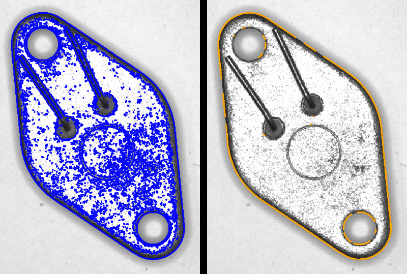
'contour_pruning': unoptimized model contours (blue) and pruned model (orange), where the contours not being representative on the given samples have been removed. Performing both the estimation of the model’s 'min_score' and the contour pruning may result in a 'min_score' that is slightly too high, as it can become overfitted to the provided samples.
Because the 'min_score' estimated with the 'linear' method can subsequently be adjusted manually, we recommend using 'linear' instead of 'per_level' when combining parameter estimation with contour optimization.
Training the shape model🔗
Once the model is created and all parameters modifying the model are set, it is time to train the model to find the
object. This is done using train_generic_shape_model, where the shape is presented via the Template. The
model parameter 'needs_training' is changed to 'false' (see get_generic_shape_model_param).
Model from XLD
Note that if you derive your model from an XLD contour, after a first match, it is strongly recommended to
determine the polarity information for the model with set_shape_model_metric.
Inspecting the shape model🔗
You can apply the operator inspect_shape_model to the template image to try different values for the parameters 'num_levels' and contrast parameters.
The operator returns the resulting representation of a shape model with multiple pyramid levels and thus allows you to visually check if the object of interest is represented adequately by the model.
If several combinations of parameter values do not lead to a satisfying representation of the object, maybe the template image, that is, the model’s ROI was not selected properly.
If you want to visually inspect an already created shape model, you can use get_generic_shape_model_object to get the XLD contours that represent the model in a specific pyramid level.
Note that the contours are stored within the model handle and you can inspect them also using the handle inspect.
To inspect the current parameter values of a model, you query them with get_generic_shape_model_param or inspect them using the handle inspect.
This may be necessary if during the creation of the model an automatic parameter selection was used or if the model was created within another program, saved to file with write_shape_model, and read from this file in the current program with read_shape_model.
Additionally, you can query the coordinates of the origin of the model using get_shape_model_origin.
You still can change model parameters using set_generic_shape_model_param, even for a trained model, but 'needs_training' will be changed to 'true' and necessitates to retrain the model .
Finding object instances🔗
This section addresses the search of model instances.
Shape-based matching uses the operator find_generic_shape_model to find object instances and the results can be retrieved using get_generic_shape_model_result and get_generic_shape_model_result_object for iconic results.
We discuss different concepts with the corresponding search parameters to optimize your specific search problem, namely:
- Modify allowed instances
- restrict model orientation
- Sort out found matches
- specify the visibility of the object
- search for multiple instances of the object
- sort out matches according to their overlap
- restrict the search by specifying clutter
- Consider accuracy
- specify the needed accuracy
As prerequisite you need a trained model with suitable settings of parameters modifying the model itself.
Restricting the model orientation🔗
Shape models created with create_generic_shape_model have a rotation range from 0 to 6.28 (\(=2\pi\)).
Thereby the range of rotation is defined relative to the reference image, that is, a starting angle of 0 corresponds to the orientation the object has in the reference image.
This range of orientation can be restricted, meaning find_generic_shape_model searches model instances of different angles within the range defined by 'angle_start' and 'angle_end'.
In case the range is not a multiple of the step size the start and end value are automatically adapted (see also the section “Automatic modifications” in set_generic_shape_model_param).
In certain cases it is advantageous to restrict the model orientation:
-
If you are only interested in matches within a certain orientation.
-
If the object is (almost) symmetric you should limit the allowed range during the search by
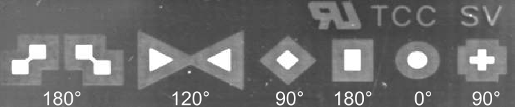
find_generic_shape_model. Otherwise, the search process will find multiple, almost equally good matches on the same object at different angles. Which match (at which angle) is returned as the best can therefore change seemingly random from image to image. The suitable range of rotation depends on the symmetry: For a cross-shaped or square object the allowed extent must be less than 90◦, for a rectangular object less than 180◦, and for a circular object 0◦ (see Figure 6). To limit the range you can set'angle_start'or'angle_end'usingset_generic_shape_model_param.
Specifying the visibility of the object🔗
Affected parameter
'min_score'
With the parameter 'min_score' you can specify how much of the model must be visible.
A typical use of this mechanism is to allow a certain degree of occlusion as demonstrated in Figure 7:
The security ring is found if 'min_score' is set to 0.7.
Let’s take a closer look at the term “visibility”: When comparing a part of a search image with the model, the matching process calculates the so-called score, which is primarily a measure of how many model points could be matched to points in the search image (ranging from 0 to 1). A model point may be “invisible” and thus not matched because of multiple reasons:
- Parts of the object’s contour are occluded, for example, as depicted in Figure 7.
Please note that by default it depends on your system settings whether objects which are clipped at the image border are found.
This behavior can be changed with set_generic_shape_model_param (
ModelID,'border_shape_models','true'). An example is%HALCONEXAMPLES%\hdevelop\Applications\Position-Recognition-2D\matching_image_border.hdev.
model of the security ring,
search result for ’MinScore’ =0.8,
search result for ’MinScore’ = 0.7.
-
Parts of the contour have a contrast lower than specified in the parameter
'min_contrast'. -
The polarity of the contrast changes globally or locally.
-
If the object is deformed, which includes also the case that the camera observes the scene under an oblique angle, parts of the contour may be visible but appear at an incorrect position and therefore do not fit the model anymore. In such cases the following options may help:
-
Deformed objects might be found if you set the parameter
'max_deformation'. -
Deformed or defocused objects might be found if the increased tolerance mode is activated, see
'pyramid_level_robust_tracking'inset_generic_shape_model_param. -
Handle perspective deformations that occur because of an oblique camera view.
-
Further potential reasons
Besides these obvious reasons, which have their root in the search image, some effects can be caused by the matching process itself:
-
HALCON pre-computes the model for intermediate angles within the allowed range of orientation. During the search, a candidate match is then compared to all precomputed model instances. A not-suitable value for the parameter
'angle_step'may lead to a significant score drop. Note, the same line of reasoning occurs also for model scaling. -
Another stumbling block lies in the use of an image pyramid: When comparing a candidate match with the model, the specified minimum score must be reached on each pyramid level.
On different levels the score may vary, with only the score on the lowest level being returned in the parameter 'score'.
This sometimes leads to the apparently paradox situation that 'min_score' must be set significantly lower than the resulting 'score'.
Note that if the matches are not tracked to the lowest pyramid level it might happen that instances with a score slightly below 'min_score' are found.
Tip
The higher 'min_score' , the faster the search!
To automatically determine a suitable value based on provided sample images you can use extended parameter estimation.
Searching for multiple instances of the object🔗
Affected parameter
'num_matches'
The maximal number of returned instances can be determined using 'num_matches'.
Its exact behavior depends on whether clutter is set, see also set_generic_shape_model_param.
Note, in case of no clutter set, promising matches are limited on every pyramid level to the number 'num_matches'.
This may result in rejecting instances on a certain pyramid level even though they would achieved a higher score on a lower pyramid level.
As a consequence it is possible that you obtain a different instance (with a lower score) by setting 'num_matches' to 1 than the instance found with highest score by setting 'num_matches' to a higher number or even 'all'.
Sorting out matches according to their overlap🔗
Affected parameter
'max_overlap'
The parameter, 'max_overlap', lets you specify how much two matches may overlap (as a fraction).
In
the two security rings overlap by a factor of approximately 0.2.
In order to speed up the matching as much as possible, the overlap is calculated neither for the models themselves nor for the models ROI but for their smallest surrounding rectangle. This must be kept in mind when specifying the maximum overlap. In most cases, therefore a larger value is needed (compare and )
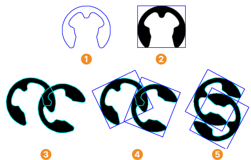
model of the security ring,
smallest rectangle surrounding the model,
model overlap,
rectangle overlap,
pathological case.
A “pathological” case is shown in : Even though the rings themselves do not overlap, their surrounding rectangles do to a large degree. Unfortunately, this effect cannot be prevented.
Restricting the search by specifying clutter🔗
Affected parameter
'clutter_region'
In some cases, although multiple matches with high 'score' values are found within a search image, not all of them are wanted as results.
For example, in Figure 9, although only the structures consisting of eight dots are searched for, more instances are found.
In order to get only the wanted matches, the instances have to be distinguished. This can be done considering the absence of edges in the neighborhood of the object as a distinctive feature.
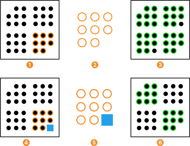
select shape model (orange) from image
extracted shape model,
matching results (green) without the use of clutter parameters (note, for visualization purpose not all rotated matches are shown),
additionally define clutter region (blue),
shape model (orange), extended by a clutter region (blue)
matching result (green) with the use of clutter parameters.
To restrict the search to candidates that have no (or too faint) edges within a region specified relative to the model contours, you can use set_generic_shape_model_object to set a clutter region via 'clutter_region'.
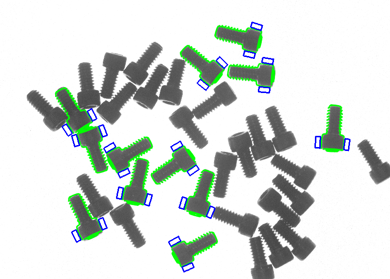
The example program %HALCONEXAMPLES%\solution_guide\matching\pick_and_place_2d.hdev uses clutter to identify the objects with enough free space so a robot can pick them, see Table 2.
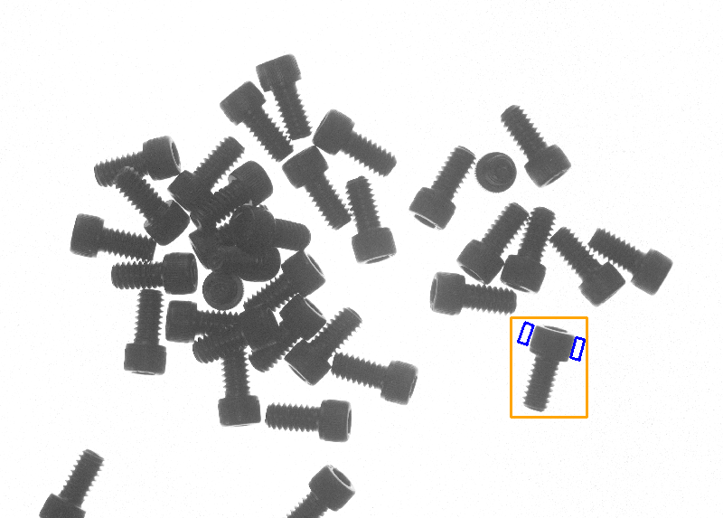 |
 |
|---|---|
| Regions to define the model (orange) and the clutter region (blue). | Search image with found instances (green) and their corresponding clutter regions (blue). |
Setting the clutter region
Follow along with the example program %HALCONEXAMPLES%\solution_guide\matching\pick_and_place_2d.hdev.
How to set a clutter region differs according to whether it is set before or after the training. In both cases, make sure that the clutter region does not contain negative coordinates and that it does not intersect the model contours.
Before the training the clutter region can be specified with regard to the template used for training.
The transformation is estimated automatically in train_generic_shape_model when setting the selected region as the clutter region.
create_generic_shape_model (ModelID)
set_generic_shape_model_object (ClutterRegion, ModelID, 'clutter_region')
train_generic_shape_model (ImageReduced, ModelID)
A clutter region can also be specified after training, in relation to an instance found on a search image. Thus, also the transformation matrix describing the respective instance position needs to be set.
Initially, we generate a model (without clutter) and train it.
create_generic_shape_model (ModelXLDID)
train_generic_shape_model (ModelXLD, ModelXLDID)
We open the image we want to use to define the clutter region. In this image we search for a model instance which we could use to define the clutter region. In the following code snippet it is Match 1.
find_generic_shape_model (Image, ModelXLDID, MatchResultDefID, NumMatchResult)
Match := 1
get_generic_shape_model_result_object (Objects, MatchResultDefID, Match, 'contours')
get_generic_shape_model_result (MatchResultDefID, Match, 'hom_mat_2d', HomMat2D)
For the found model instance we define the respective clutter region, set the clutter region, ’clutter_region’, and use the transformation matrix of the found model instance, ’HomMat2D’, to define the clutter transformation ’clutter_hom_mat_2d’.
set_generic_shape_model_object (ClutterRegion, ModelXLDID, 'clutter_region')
set_generic_shape_model_param (ModelXLDID, 'clutter_hom_mat_2d', HomMat2D)- Clutter and speed
-
Setting clutter is suitable to select matches but contrary to other options it does not reduce the runtime. Clutter regions have their impact only at the end of the matching pipeline. This means, possible candidates are tracked through the image pyramid and only at the end the clutter region is checked based on the set clutter parameters.
Thus, no candidate is rejected when tracking the candidates through the image pyramid. As a consequence, the runtime for a search using clutter is always at least as high as when returning all matches.
Specifying the needed accuracy🔗
Affected parameter
'max_deformation'
Different aspects can affect the accuracy of a match, for example, how precisely it is located (refinement: 'subpixel'), if it is slightly deformed ('max_deformation'), or its point of reference may be inapt.
In this section we will have a look at these influences.
The matching process locates found instances in two steps:
-
Find coarse matches
-
Refine the matches
In the first step matches are located with an accuracy of 1 pixel for the position ('row', 'column') while the accuracy of the orientation and scale is equal to the values selected for the parameters 'angle_step' and 'scale_step' (or the corresponding parameters for anisotropic scaling), respectively.
The following refinement is optional and can be determined using the parameter 'subpixel':
'none'- No refinement is performed.
'interpolation'-
HALCON examines the matching scores at the neighboring positions, angles, and scales around the best match and determines the maximum by interpolation. Using this method, the position is therefore estimated with subpixel accuracy (≈ 120 pixel can be achieved).
The accuracy of the estimated orientation and scale depends on the size of the object, like the optimal values for the parameters
'angle_step'and'scale_step'or the corresponding parameters for anisotropic scaling: The larger the size, the more accurately the orientation and scale can be determined. 'least_squares','least_squares_high', or'least_squares_very_high'- A least-squares adjustment is used instead of an interpolation, resulting in a higher accuracy. However, this method requires additional computation time.
A note regarding the interplay with the score:
While the refinement using the parameter 'subpixel' improves the position, orientation, and scale of a match, it does not update its score.
As mentioned above, in the first step the matches are located with an accuracy of 1 pixel. As a consequence, models that solely differ in their reference point may find the corresponding match with different scores, if the reference points do not differ by an integer in both directions.
Sometimes objects are not found or found only with a low accuracy because they are slightly deformed compared to the model.
If your object is most probably deformed, you can allow a maximum deformation of a few pixels for the model by setting 'max_deformation' using set_generic_shape_model_param.
For example, if you set 'max_deformation' to 2, the contour of the searched object may differ by up to two pixels from the shape of the model.
To get a meaningful score value and to avoid erroneous matches, we recommend to always combine the allowance of a deformation with a least-squares adjustment.
Note that high values for the maximal allowed deformation increase the runtime and the risk of finding wrong model instances, especially for small models.
Thus, the value should be chosen as small as possible but as high as necessary.
Using 'max_deformation', the tracking of candidates through the image pyramid stops at pyramid level \(\max(\lfloor \log_2(\mathrm{'max\_deformation'}) \rfloor + 1, \mathrm{'pyramid\_level\_lowest'})\).
Thus, as the impact of deformations on the contours increases on lower pyramid levels, tracking may stop on a higher level than 'pyramid_level_lowest', and the candidate is projected down to 'pyramid_level_lowest'.
The match score calculation and final position refinement are performed on 'pyramid_level_lowest'.
Nevertheless, the match is returned on the first pyramid level, thus the original image.
Modified point of reference
Please note that the accuracy of the estimated position may decrease if you modify the point of reference (for example, using set_shape_model_origin or set_generic_shape_model_param).
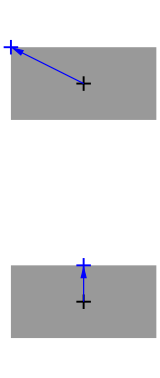
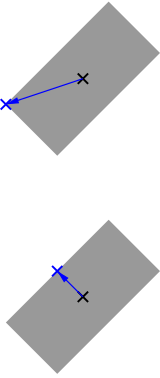
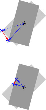
This effect is visualized in Table 2: As you can see in the right-most column, an inaccuracy in the estimated orientation “moves” the modified point of reference, while the original point of reference is not affected. The resulting positional error depends on multiple factors, for example, the offset of the point of reference and the orientation of the found object.
The main point to keep in mind is that the error increases linearly with the distance of the modified point of reference from the original one (compare the two rows in Table 2).
An inaccuracy in the estimated scale also results in an error in the estimated position, which again increases linearly with the distance between the modified and the original point of reference.
For maximum accuracy in case the point of reference is moved, the position should be determined using the least-squares adjustment. Note that the accuracy of the estimated orientation and scale is not influenced by modifying the point of reference.
| model | rotation | rotation inaccuracy |
|---|---|---|
 |
 |
 |