Calibration object🔗
Describing the calibration object🔗
With the operator set_calib_data_calib_object, you specify the needed information about the calibration object.
If you are using a HALCON calibration plate, the name of the corresponding description file is sufficient.
set_calib_data_calib_object (CalibDataID, 0, 'calplate_80mm.cpd')How to obtain a HALCON calibration plate is explained in Frequently asked questions about the calibration process.
However, you can also use your own calibration object. Then, you pass the coordinates of the markers instead of the file name to the operator.
Obtaining a suitable calibration plate🔗
The simplest method to determine the camera parameters of a CCD camera is to use a HALCON calibration plate (see Frequently asked questions about the calibration process for examples). In this case, the whole process of finding the calibration plate, extracting the calibration marks, and determining the correspondences between the extracted calibration marks and the respective 3D world coordinates can be carried out automatically. Even more important, these calibration plates are highly accurate, down to 1 μm or below, which is a prerequisite for high accuracy applications. Therefore, we recommend to obtain such a calibration plate from the local sales partner from which you purchased HALCON.
| Hexagonal arrangement | Rectangular arrangement |
|---|---|
 |
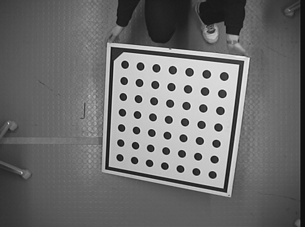 |
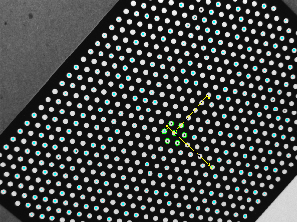
Two types of HALCON calibration plates are supported. In particular, calibration plates with hexagonally arranged marks and calibration marks with rectangularly arranged marks are available. The calibration plates with hexagonally arranged marks are introduced with HALCON 12 and are recommended for most applications, as they provide the following advantages compared to the calibration plates with rectangularly arranged marks:
- The calibration plates with rectangularly arranged marks must be completely visible in the images whereas plates with hexagonally arranged marks may protrude beyond the rim of the image. Thus, with the latter less care must be taken when placing the calibration plate in the images. The acquisition of the calibration images becomes faster and more convenient without a loss of robustness.
- As calibration plates with hexagonally arranged marks contain a significantly larger number of calibration marks and can protrude beyond the rim of the image, less care is needed to get a comparable calibration result.
The calibration plates are available in different materials (ceramics for front light, glass for back light applications, aluminum for very large calibration plates) and sizes. Thus, you can choose the one that is optimal for your application. Detailed information about the available materials, sizes, and the accuracy can be obtained from your local sales partner.
The main differences between the calibration plates with hexagonally arranged marks and the calibration plates with rectangularly arranged marks are:
- Different arrangement of the marks: For calibration plates with hexagonally arranged marks the marks are arranged in a hexagonal lattice such that each mark has six equidistant neighbors whereas calibration plates with rectangularly arranged marks are arranged in a rectangular grid with equidistant rows and columns.
- Different number of contained marks: Calibration plates with hexagonally arranged marks have a significantly larger number of marks than calibration plates with rectangularly arranged marks.
- Different special patterns: The calibration plates with hexagonally arranged marks contain one to five unique finder patterns, i.e., special mark hexagons (each consisting of a mark and its six neighbors) where either four or six marks contain a hole.
To find the calibration plate in the image and estimate the pose of it relative to the observing camera using
find_calib_object, at least one finder pattern must be completely visible in the image. The calibration plates with rectangularly arranged marks contain a triangular orientation mark and a surrounding frame. Here, the complete calibration plate must be visible to find the plate and estimate its pose. - Different origin: The coordinate system of the calibration plate with hexagonally arranged marks is located at the center of the central mark of the first finder pattern whereas the coordinate system of the calibration plate with rectangularly arranged marks is located in the barycenter of all marks.
- Slightly different handling: Due to the differences described above, the rules for the acquisition of calibration images differ in some points. First of all, for calibration plates with hexagonally arranged marks less calibration images are needed and the calibration plates do not have to be completely visible in the image. For more information, see “How to take a set of suitable images?”.
Each calibration plate comes with a description file.
Place this file in the subdirectory calib of the directory where you installed HALCON.
Then, you can use its file name directly in the operator caltab_points.
Note
The description files for calibration plates with hexagonally arranged marks have the file extension ‘.cpd’ and those of the calibration plates with rectangularly arranged marks have the file extension ‘.descr’.
Calibration plates with rectangularly arranged marks always have dark marks on a light background, whereas calibration plates with hexagonally arranged marks usually have light marks on a dark background. Nevertheless, also calibration plates with dark hexagonally arranged marks on a light background are available, e.g., for back light applications. The corresponding description files are indicated by the suffix ‘dark_on_light’.
For test purposes, you can create a calibration plate yourself with the operator create_caltab for calibration plates with hexagonally arranged marks and with the operator gen_caltab for calibration plates with rectangularly arranged marks.
Print the resulting PostScript file and mount it on a planar and rigid surface, e.g., an aluminum plate or a solid cardboard.
If you do not mount the printout on a planar and rigid surface, you will not get meaningful results by HALCON’s camera calibration as the operators create_caltab and gen_caltab assume that the calibration marks lie within a plane.
Such self-made calibration plates should only be used for test purposes as you will not achieve the high accuracy that can be obtained with an original HALCON calibration plate.
Note that the printing process is typically not accurate enough to create calibration plates smaller than 16 cm for calibration plates with hexagonally arranged marks and 3 cm for calibration plates with rectangularly arranged marks.
Using your own calibration object🔗
With HALCON, you are not restricted to using a planar calibration object like the HALCON calibration plate. You can use a 3D calibration object or even arbitrary characteristic points (natural landmarks). The only requirement is that the 3D world position of the model points is known with high accuracy.
Then, you simply pass the 3D coordinates of all points (markers) of the calibration object as a tuple in the parameter CalibObjDescr of set_calib_data_calib_object.
All x, y, and z coordinates of all points must be packed sequentially in the tuple in the form [X, Y, Z].
Note however, that if you use your own calibration object, you cannot use the operator find_calib_object anymore.
Instead, you must determine the 2D locations of the model points and the correspondence to the 3D points by yourself.
Observing the calibration object in multiple poses (images)🔗
The main input data for the calibration are the so-called observations. For this, the calibration object is placed in different poses. For each pose, the camera acquires an image. In this image, the markers of the calibration object are extracted, and their (pixel) coordinates, together with the indices of camera, calibration object, and calibration object pose and with a tuple containing the indices of the corresponding markers, are stored in the calibration data model.
If you are using a standard HALCON calibration plate, you can apply the extraction of the coordinates with the operator find_calib_object, which automatically stores the obtained information, including the coordinates of the markers and the list of marker correspondences, in the calibration data model.
for I := 1 to NumImages by 1
    read_image (Image, ImgPath + 'calib_image_' + I$'02d')
    find_calib_object (Image, CalibDataID, 0, 0, I, [], [])
endfor
If you are using your own calibration object, you must extract its markers and determine the correspondences by yourself and then store the information into the calibration data model with set_calib_data_observ_points.
Acquiring calibration images🔗
If you want to achieve accurate results, please follow the recommendations given in the section “How to take a set of suitable images?”. It gives guidance regarding the placement of the calibration plates, the camera setup and the image properties.
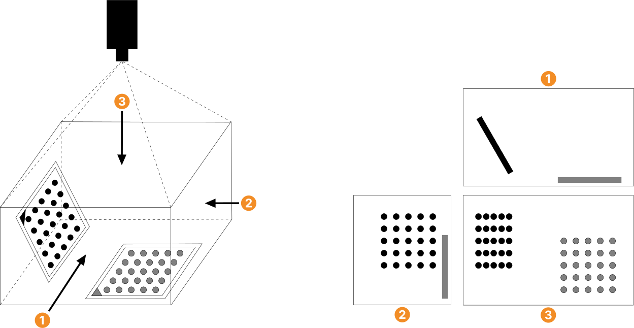
Note that a good calibration result can be obtained only for a distribution of the calibration marks within the full field of view of the camera. You can imagine the part of the 3D space that corresponds to the field of view as a calibration volume like shown in Figure 1. There, two poses of calibration plates and the positions of their calibration marks, when seen from different views, are illustrated. You can see, e.g., in the view from , that large parts are not covered by marks. To get a full distribution of the marks and thus enable a good calibration result, you have to place the calibration plates in your other images so that the empty parts of the calibration volume are minimized for all views. Be aware that when having very small calibration plates (compared to the field of view), this means that it may be necessary to use significantly more than the recommended number of calibration images.
If only one image is used for the calibration process or if the orientations of the calibration plate do not vary over the different calibration images, it is not possible to determine both the focal length and the pose of the camera correctly; only the ratio between the focal length and the distance between calibration plate and camera can be determined in this case. Nevertheless, it is possible to measure world coordinates in the plane of the calibration plate. When measuring outside the plane onto which the calibration plate was placed, you will get systematic errors.
The accuracy of the resulting world coordinates depends very much on the number of images used for the calibration process, apart from the measurement accuracy in the image. The more images (with significantly different calibration plate poses) are used, the more accurate results will be achieved.
Extracting the marks of a HALCON calibration plate🔗
The operator find_calib_object searches for the calibration plate, determines the image coordinates of the calibration marks with high precision, and stores the results in a calibration data model.
The calibration mark contours can be accessed with the operator get_calib_data_observ_contours.
If the calibration object is no standard HALCON calibration plate set_calib_data_observ_points needs to be used.
Restricting the calibration to specific parameters🔗
If certain camera parameters are already known, you can exclude them from the calibration with the operator set_calib_data.
Analogously, you can restrict the calibration to certain parameters.
Performing the calibration🔗
After preparing the calibration data model as described in the previous sections, you perform the calibration by calling the operator calibrate_cameras, using the calibration data model as input.
calibrate_cameras (CalibDataID, Errors)As a direct result, only the calibration error is returned.
It corresponds to the average distance (in pixels) between the backprojected calibration points and their extracted image coordinates.
An error of up to 0.1 pixels indicates that the calibration was successful.
You can further analyze the quality of the calibration results with the operator get_calib_data.
The main results of the calibration, e.g., the internal camera parameters, are stored in the calibration data model. How to access them is described in the following section.
Accessing the results of the calibration🔗
The main results of the operator calibrate_cameras comprise the internal camera parameters and the pose of the calibration plate in each of the images from which the corresponding points were determined.
The operator stores them in the calibration data model.
You can access them with the operator get_calib_data.
The example program CalibrationInternalDev shows how to access the internal camera parameters and write them into a file.
get_calib_data (CalibDataID, 'camera', 0, 'params', CamParam)
write_cam_par (CamParam, 'camera_parameters.dat')
The external camera parameters cannot be queried directly, because the needed information about the world coordinate system is not stored in the calibration data model.
However, if the calibration plate was placed directly on the measurement plane, its pose can be used to easily derive the external camera parameters, which are the pose of the measurement plane. This is described in the following section.
Determining the external camera parameters🔗
The external camera parameters describe the relation between the measurement plane and the camera, i.e., only if the external parameters are known it is possible to transform coordinates from the camera coordinate system (CCS) into the coordinate system of the measurement plane and vice versa. In HALCON, the measurement plane is defined as the plane \(z=0\) of the world coordinate system (WCS).
The external camera parameters can be determined in different ways:
-
Use the pose obtained from one of the calibration images in which the calibration plate is placed directly on the measurement plane. In this case, you just need to access this pose with the operator
get_calib_data. -
Separate the determination of the internal camera parameters from the determination of the external camera parameters by using an additional image in which the calibration plate is placed directly on the measurement plane. Apply
find_calib_objectto extract the calibration marks and the pose. -
Determine the correspondences between 3D world points and their projections in the image by yourself and then call
vector_to_pose.
If you only need to accurately measure the dimensions of an object, regardless of the absolute position of the object in a given coordinate system, one of the first two cases can be used.
The latter two cases have the advantage that the external camera parameters can be determined independently from the internal camera parameters. This is more flexible and might be useful if the measurements should be done in several planes from a single camera or if it is not possible to calibrate the camera in situ.
In the following, the different cases are described in more detail.
Placing the calibration plate on the measurement plane in one of the calibration images🔗
The first case is the easiest way of determining the external parameters. The calibration plate must be placed directly on the measurement plane, e.g., the assembly line, in one of the (many) images used for the determination of the internal parameters.
Since the pose of the calibration plate is determined by the operator calibrate_camerasxspace, you can simply access its pose with the operator get_calib_data.
This way, internal and external parameters are determined in one single calibration step as is shown in the HDevelop example program CalibrationMultiImageDev.
Here, the pose of the calibration plate (calibration object index 0) in the first calibration image is determined.
Each pose consists of seven values.
get_calib_data (CalibDataID, 'calib_obj_pose', [0, 1], 'pose', Pose)The resulting pose would be the true pose of the measurement plane if the calibration plate were infinitely thin.
Because real calibration plates have a thickness \(d > 0\), the pose of the calibration plate is shifted by an amount \(-d\) perpendicular to the measurement plane, i.e., along the \(z\) axis of the WCS.
To correct this, we need to shift the pose by \(d\) along the \(z\) axis of the WCS.
To perform this shift, you can use the operator set_origin_pose.
set_origin_pose (Pose, 0, 0, 0.002, Pose)In general, the calibration plate can be oriented arbitrarily within the WCS as long as the spatial relation between the calibration plate and the measurement plane is known (see Figure 2). Then, to derive the pose of the measurement plane from the pose of the calibration plate, a rigid transformation is necessary. In the following example, the pose of the calibration plate is adapted by a translation along the \(y\) axis followed by a rotation around the \(x\) axis.
pose_to_hom_mat3d (FinalPose, HomMat3D)
hom_mat3d_translate_local (HomMat3D, 0, 3.2, 0, HomMat3DTranslate)
hom_mat3d_rotate_local (HomMat3DTranslate, rad(-14), 'x', HomMat3DAdapted)
hom_mat3d_to_pose (HomMat3DAdapted, PoseAdapted)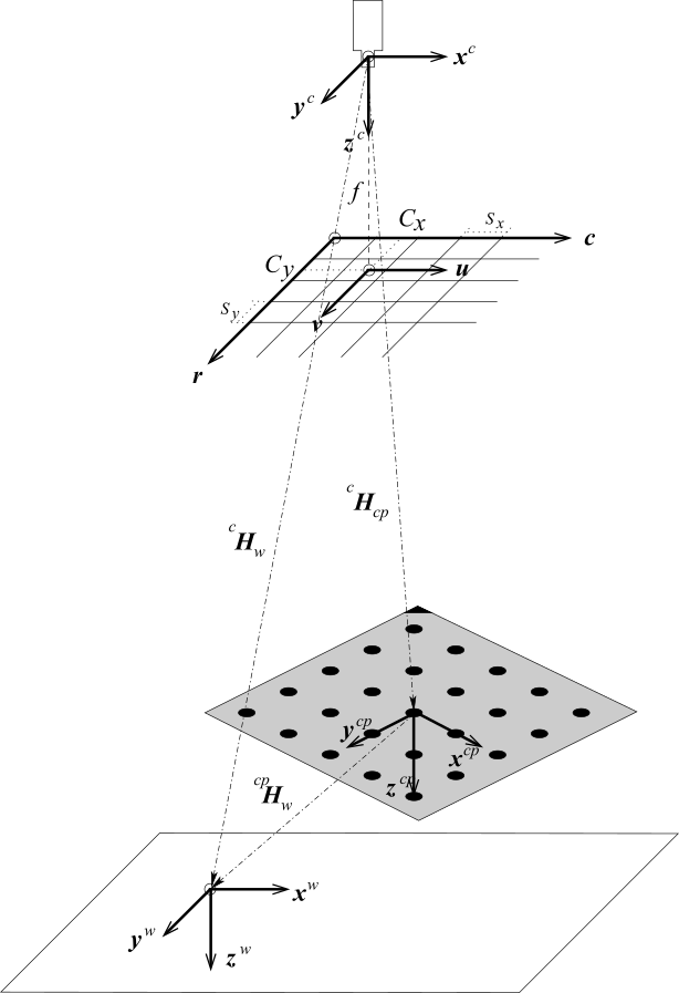
Camera coordinate system \((x^c, y^c, z^c)\)
World coordinate system \((x^w, y^w, z^w)\)
Calibration plate coordinate system \((x^cp, y^cp, z^cp)\)
Image plane coordinate system \((u, v)\)
Image coordinate system \((r ,c)\)
Placing the calibration plate on the measurement plane in a separate image🔗
If the advantages of using the HALCON calibration plate should be combined with the flexibility given by the separation of the internal and external camera parameters the second method for the determination of the external camera parameters can be used.
First, the camera is calibrated as described in the previous sections. This can be done, e.g., prior to the mounting of the camera at its final usage site.
Then, after setting up the camera at its final usage site, the external parameters can be determined.
The only thing to be done is to take an additional image in which the calibration plate is placed directly on the measurement plane.
From this image the external parameters can be determined as is shown in the example program %HALCONEXAMPLES%\solution_guide\3d_vision\camera_calibration_external.hdev.
There, the internal camera parameters, the image in which the calibration plate was placed directly on the measurement plane, and the world coordinates of the calibration marks are read from file.
read_cam_par ('camera_parameters.dat', CamParam)
read_image (Image, ImgPath + 'calib_11')
Then, the calibration marks and the pose of the calibration plate are extracted.
find_calib_object (Image, CalibDataID, 0, 0, 1, [], [])Finally, to take the thickness of the calibration plate into account, the \(z\) value of the origin given by the camera pose is translated by the thickness of the calibration plate.
set_origin_pose (PoseForCalibrationPlate, 0, 0, 0.00075, PoseForCalibrationPlate)Note that it is very important to fix the focus of your camera if you want to separate the calibration process into two steps as described in this section, because changing the focus is equivalent to changing the focal length, which is part of the internal parameters.
Using known 3D points and their corresponding image points🔗
If it is necessary to perform the measurements within a given world coordinate system, the third case for the determination of the external camera parameters can be used.
Here, you need to know the 3D world coordinates of at least three points that do not lie on a straight line.
Then, you must determine the corresponding image coordinates of the projections of these points.
Now, the operator vector_to_pose can be used for the determination of the external camera parameters.
An example for this possibility of determining the external parameters is given in the following program. First, the world coordinates of three points are set.
X := [0, 50, 100, 80]
Y := [5, 0, 5, 0]
Z := [0, 0, 0, 0]
Then, the image coordinates of the projections of these points in the image are determined. In this example, they are simply set to some approximate values. In reality, they should be determined with subpixel accuracy since they define the external camera parameters.
RCoord := [414, 227, 85, 128]
CCoord := [119, 318, 550, 448]
Finally, the operator vector_to_pose is called with the correspondences and the internal camera parameters.
vector_to_pose (X, Y, Z, RCoord, CCoord, CamParam, 'iterative', 'error', FinalPose, Errors)Again, it is very important to fix the focus of your camera because changing the focus is equivalent to changing the focal length, which is part of the internal parameters.
Deleting observations from the calibration data model🔗
To determine the effect of an observation on the calibration or to remove observations of bad quality from the calibration data model, an observation can be deleted using the operator remove_calib_data_observ.
For acquiring calibration images of suitable quality please refer to the recommendations listed in the section “How to take a set of suitable images?”.
RemoveObservationIdx := 3
remove_calib_data_observ (CalibDataID, 0, 0, RemoveObservationIdx)