About multi-view calibration🔗
To achieve high accuracy for your measuring tasks, you need to calibrate your camera setup. In comparison to a single-camera setup, some additional requirements apply to the calibration of a multi-view camera setup.
More Info
The following paragraphs provide explanations regarding the calibration of multi-view camera setups. For general information about camera calibration, see Camera calibration.
About different camera types🔗
Projective area scan cameras🔗
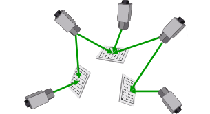
For a setup with projective area scan cameras, perform the calibration as depicted in Workflow for multi-view camera calibration. The algorithm tries to build a chain of observation poses that connects all cameras and calibration object poses to the reference camera like in the diagram below.
 |
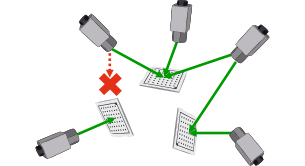 |
Figure 1.
All cameras can be connected by a chain of observation poses.
The leftmost camera is isolated, because the left calibration plate cannot be seen by any other camera.
Possible projective area scan cameras are:
-
'area_scan_division' -
'area_scan_polynomial' -
'area_scan_tilt_division' -
'area_scan_tilt_polynomial' -
'area_scan_tilt_image_side_telecentric_division' -
'area_scan_tilt_image_side_telecentric_polynomial' -
'area_scan_hypercentric_division' -
'area_scan_hypercentric_polynomial'
Telecentric area scan cameras🔗
For a setup with telecentric area scan cameras, the same steps from Workflow for multi-view camera calibration are executed, similar to projective area scan cameras.
In the first step (building a chain of observation poses that connects all cameras and calibration objects), additional conditions must hold:
- As the pose of an object can only be determined up to a translation along the optical axis, each calibration object must be observed by at least two cameras to determine its relative location. Otherwise, its pose is excluded from the calibration.
- As a planar calibration object appears the same from two different observation angles, the relative pose of the cameras among each other cannot be determined unambiguously.
Therefore, there are always two valid alternative relative poses.
Both alternatives result in a consistent camera setup, which can be used for measuring. As the ambiguity cannot be resolved, the first of the alternatives is returned. If the returned pose is not the real pose but the alternative one, then this will result in a mirrored reconstruction.
Possible telecentric area scan cameras are:
-
'area_scan_telecentric_division' -
'area_scan_telecentric_polynomial' -
'area_scan_tilt_bilateral_telecentric_division' -
'area_scan_tilt_bilateral_telecentric_polynomial' -
'area_scan_tilt_object_side_telecentric_division' -
'area_scan_tilt_object_side_telecentric_polynomial'
Projective and telecentric area scan cameras🔗
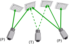
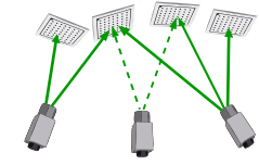
For a mixed setup with projective and telecentric area scan cameras, the algorithm performs the same Workflow for multi-view camera calibration. As described above for telecentric cameras, possible ambiguities during the first step (building a chain of observation poses that connects all cameras and calibration objects), can be resolved as long as there exists a chain of observation poses consisting of all perspective cameras and a sufficient number of calibration objects. Here, sufficient number means that each telecentric camera observes at least two calibration objects of this chain.
  |
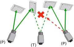 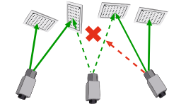 |
Figure 2. Mixed calibration setup with perspective (P) and telecentric (T) area scan cameras.
All perspective cameras are connected by a chain of observation poses that only contains perspective cameras.
The second calibration plate (from the left) is not observed by the rightmost perspective camera. Therefore, the relative pose between both perspective cameras cannot be determined uniquely.
Line scan cameras🔗
Setups with telecentric line scan cameras ('line_scan_telecentric') behave identically to setups with telecentric area scan cameras and the same restrictions and ambiguities that are described above apply.
For this type of setup, two possible configurations can be distinguished:
-
In the first configuration, all cameras are mounted rigidly and stationary and the object is moved linearly in front of the cameras. Alternatively, all cameras are mounted rigidly with respect to each other and are moved across the object by the same linear actuator. In both cases, all cameras share a common motion vector, which is modeled in the camera coordinate system of the reference camera and is transformed to the camera coordinate systems of all other cameras by the rotation part of the respective camera’s pose.
This configuration is assumed by default. -
In the second configuration, the cameras are moved by independent linear actuators in different directions. In this case, each camera has its own independent motion vector.
The type of configuration can be selected with set_calib_data.
 |
 |
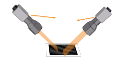 |
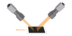
Figure 3. Different configurations of telecentric line scan camera setups can be distinguished:
Only one motion vector needs to be computed if the cameras are mounted stationary while the object is moved linearly,
or if the cameras are moved across the object while mounted rigidly to each other.
Alternatively, if the cameras are moved independently from each other, a motion vector is determined for each camera.
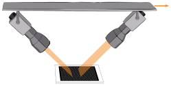
Two different stereo setups are common for telecentric line scan cameras. For both setups, a linear, constant motion is assumed for the observed object or the camera system, respectively.
-
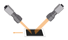
For along-track setups, one camera is placed in front, looking in backwards direction, while the second camera is mounted behind, looking forwards, both at an suitable angle in respect to the motion vector.
-
The cameras in an across-track setup are all directed perpendicular to the motion vector, while the viewing planes are approximately coplanar. Therefore, the depth of field is rather limited. Precise measurements are only possible in areas where the depth of field of the individual cameras overlap.
 |
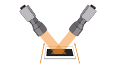 |
Figure 4. Stereo setups for telecentric line scan cameras:
Along-track setup
Across-track setup
For setups with projective line scan cameras ('line_scan'), the following restriction exists:
Only one camera can be calibrated and only one calibration object per setup can be used.
Finally, for calibration plates with rectangularly arranged marks (see gen_caltab), all observations must contain the projection coordinates of all calibration marks of the calibration object.
For calibration plates with hexagonally arranged marks (see create_caltab), this restriction does not apply.
For more information about calibration plates and the acquisition of calibration images, see also Fequently asked questions about the calibration process.
Checking the success of the calibration🔗
If more than one camera is calibrated simultaneously, the value of Error is more difficult to judge.
As a rule of thumb, Error should be as small as possible and at least smaller than 1.0, thus indicating that a subpixel precise evaluation of the data is possible with the calibrated parameters.
This value might be difficult to reach in particular configurations.
For further analysis of the quality of the calibration, refer to the standard deviations and covariances of the estimated parameters.
Getting the calibration results🔗
The results of the calibration, that is, internal camera parameters, camera poses (external camera parameters), calibration objects poses etc., can be queried with get_calib_data.
Poses of telecentric cameras can only be determined up to a displacement along the z-axis of the coordinate system of the respective camera (perpendicular to the image plane). Therefore, all camera poses are moved along this axis until they all lie on a common sphere. The center of the sphere is defined by the pose of the first calibration object. The radius of the sphere depends on the calibration setup.
If projective and telecentric area scan cameras are calibrated, the radius is the maximum over all distances from the perspective cameras to the first calibration object. Otherwise, if only telecentric area scan cameras are considered, the radius is equal to 1 m.