Camera calibration🔗
More Info
Learn about camera calibration, hand-eye calibration, and many other topics in interactive online courses at our MVTec Academy.
General objectives🔗
To achieve maximum accuracy of measurement for your camera setup, you have to calibrate it accordingly. Therefore, a camera model is determined, which describes the projection of a 3D world point into a (sub-)pixel in the image.
HALCON provides a wide range of operators to approach diverse tasks related to calibration, such as
- describing and finding a calibration object
(operators: Calibration > Calibration Object) - the projection of points from the 3D scene onto the image plane and the other way around
(operators: Calibration > Projection, Calibration > Inverse Projection) - compensating perspective and radial distortions
(operators: Calibration > Rectification) - handling the camera parameters
(operators: Calibration > Camera Parameters) - performing a self-calibration
(operators: Calibration > Self Calibration) - calibrating different setups consisting of
- one camera
(operators: Calibration > Monocular) - multiple cameras
(operators: Calibration > Binocular, Calibration > Multi View) - a camera in combination with a robot
(operators: Calibration > Hand Eye)
- one camera
About calibration objects🔗
For a successful calibration of your camera setup, at least one calibration object with accurately known metric properties is needed, for example, a HALCON calibration plate.
For the calibration, take a series of images of the calibration object in different positions and orientations. The success of the calibration highly depends on the quality of the calibration object and the images. Hence, you may want to exercise special diligence during the acquisition of the calibration images.
For more information, see How to take a set of suitable images?.
A calibration plate is covered by multiple calibration marks, which are extracted in the calibration images in order to retrieve their coordinates. The orientation of the plate has to be known distinctively, hence, a finder pattern is also part of the imprint.
Your local sales partner can provide you with two different types of standard HALCON calibration plates:
- Calibration plate with hexagonally arranged marks
-
As finder pattern, there are special groups of mark hexagons where some of the marks contain dot-shaped holes (see
create_caltab). One finder pattern has to be visible to locate the calibration plate. To make sure the plate is not inverted, at least a second one needs to be seen, but the plate does not have to be fully visible in the image.
The origin of the coordinate system is located at the center of the central mark of the first finder pattern. The z-axis of the coordinate system is pointing into the calibration plate, its x-axis is pointing to the right, and its y-axis is pointing downwards with the direction of view along the z-axis.When using
camera_calibrationinstead ofcalibrate_cameras, this calibration plate is not applicable.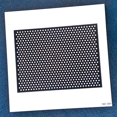
Figure 1. HALCON calibration plate with hexagonally arranged marks
- Calibration plate with rectangularly arranged marks
-
The finder pattern consists of the surrounding frame and the triangular corner marker (see
gen_caltab). Thus, the plate has to be fully visible in the image.
The origin is located in the middle of the surface of the calibration plate. The z-axis of the coordinate system is pointing into the calibration plate, its x-axis is pointing to the right, and its y-axis is pointing downwards with the direction of view along the z-axis.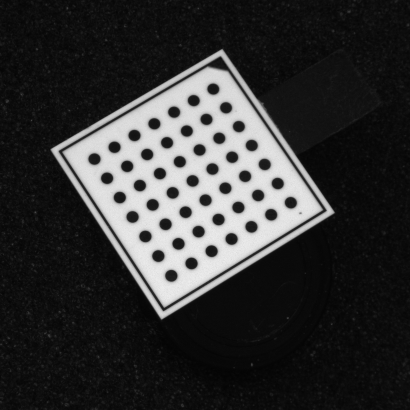
Figure 2. HALCON calibration plate with rectangularly arranged marks
When acquiring your calibration images, there are different recommendations on how to take them, depending on your used calibration plate. For more information, see How to take a set of suitable images?.
Frequently asked questions about the calibration process🔗
How to obtain an appropriate calibration plate?
You can obtain high-precision calibration plates in various sizes and materials from your local sales partner.
These calibration plates come with associated description files and can be easily extracted with find_calib_object.
It is also possible to use any arbitrary object for calibration. The only requirement is that the object has characteristic points that can be robustly detected in the image and that the 3D world position of these points is known with high accuracy.
Self-printed calibration objects are usually not accurate enough for high-precision applications.
How to take a set of suitable images?
With the combination of lens (fixed focus setting!), camera, and frame grabber to be calibrated, a set of images of the calibration plate must be taken (see open_framegrabber and grab_image).
Your local sales partner can provide you with two different types of standard HALCON calibration plates:
Calibration plates with hexagonally arranged marks (see create_caltab) and calibration plates with rectangularly arranged marks (see gen_caltab).
As these two calibration plates substantially differ from each other, in some cases additional particularities apply (see below).
The parameters and hints listed below should be considered when taking the calibration images.
For a successful calibration, the setup and the used set of images should have certain qualities.
These qualities may vary for the specific task and demand.
To give guidance, values and hints suitable for a basic monocular camera setup are mentioned.
- Camera setup
-
-
Aperture
The aperture of the camera must not be changed during the acquisition of the images. If the aperture is changed after the calibration, the camera must be calibrated anew.
-
Camera pose
The position of the camera must not be changed during the image acquisition.
-
Focus
The calibration images should be sharply focused, i.e., transitions between objects should be clearly delimited. The focus, respectively the focal length, must not be changed during the image acquisition.
-
- Placement of the calibration plates
-
-
Field of view coverage and orientation
Within the set of calibration images, every part of the field of view should be covered by the plate at least once. The calibration plate may also fill the entire image. The orientation of the plate should vary within the set of images.
-
Tilt angles
The set of calibration images should also contain images with tilted calibration plates. Thereby the plate should be tilted in different directions at an angle of about 30-45°. Note, that if the recommended angle cannot be realized due to, for example, limited depth of field, you should at least tilt your plate as steeply as possible with your setup.
-
Number of images/calibration plate poses
-
Plate with hexagonally arranged marks: at least 6 images (not all, but at least 4 of them with tilted calibration plates)
-
Plate with rectangularly arranged marks: at least 15 images
Nevertheless, ensure that the poses of the calibration plates also fulfill the other requirements.
-
-
Inverted acquisition of the calibration plate
The calibration marks must not be acquired inverted. This can, for example, happen if a calibration plate made of glass is acquired from its backside or if a line scan camera is not moving downwards with respect to the image coordinate system (i.e., Vy is negative).
-
- Image properties and content
-
-
Pattern coverage
How much of the calibration pattern must at least be contained in the images depends on the used plate.
-
Plate with hexagonally arranged marks: At least one finder pattern needs to be visible. If at least two finder patterns are visible in the image, it is possible to detect whether the calibration plate is mirrored or not. In a mirrored case, a suitable error will be returned.
-
Plate with rectangularly arranged marks: Plate needs to be completely visible, as the finder pattern is the frame surrounding the point marks.
However, the more of the calibration pattern is visible to the camera and the more of the field of view is filled by the calibration plate, the better.
-
-
Mark diameter
The marks of the calibration plates should have a diameter of at least 20 pixels in each image. This requirement is essential for a successful calibration.
-
Contrast
The contrast between the light and dark areas of the calibration plate should be at least 100 gray values (regarding byte images).
-
Overexposure
To avoid overexposed images, make sure that gray values of the light parts of the calibration plate do not exceed 240 (regarding byte images), especially not in the neighborhood of the calibration marks.
-
Homogeneity
The calibration plate should be illuminated homogeneously and reflections should be avoided. As a rule of thumb, the range of gray values of the light parts of the plate should not exceed 45 (regarding byte images).
-
- Image format and preprocessing
-
-
Image format
Calibration images should be saved in an uncompressed format. Compression artifacts occurring, for example, when using JPG format and high compression rates, need to be avoided.
-
Preprocessing
Calibration images should not be preprocessed. If image properties like contrast or focus are insufficient (see above), the issues need to be resolved by adjusting the camera setup instead of processing the images ahead of the calibration.
-
Which distortion model should be used?
Two distortion models can be used:
The division model and the polynomial model.
The division model uses one parameter to model the radial distortions, while the polynomial model uses five parameters to model radial and decentering distortions (see Camera parameters and About the used 3D camera model).
The advantages of the division model are that the distortions can be applied faster, especially the inverse distortions, i.e., if world coordinates are projected into the image plane. Furthermore, if only few calibration images are used or if the field of view is not covered sufficiently, the division model typically yields more stable results than the polynomial model.
The main advantage of the polynomial model is that it can model the distortions more accurately because it uses higher order terms to model the radial distortions and because it also models the decentering distortions.
Note that the polynomial model cannot be inverted analytically.
Therefore, the inverse distortions must be calculated iteratively, which is slower than the calculation of the inverse distortions with the (analytically invertible) division model.
Typically, the division model should be used for the calibration.
If the accuracy of the calibration is not high enough, the polynomial model can be used.
However, the calibration sequence used for the polynomial model must provide an even better coverage of the area in which measurements will later be performed.
The distortions may be modeled inaccurately outside of the area that was covered by the calibration plate.
This holds for the image border as well as for areas inside the field of view that were not covered by the calibration plate.
Further limitations related to specific camera types🔗
For pinhole cameras, if the calibration plates are parallel to each other in all images (in particular, if they all lie in the same plane), it is impossible to determine Focus together with all six of the external camera parameters.
For example, it is impossible to determine Focus and the distance of the calibration plates to the camera in this case.
To be able to calibrate all camera parameters uniquely, make sure that you acquire images of the calibration plate tilted in different orientations.
For telecentric lenses, the distance of the calibration plate from the camera cannot be determined. Therefore, the z-component of the resulting calibration plate pose is set to 1 m in the calibration results. Furthermore, as described previously, for telecentric line scan cameras, \(V_{z}\) cannot be determined and is left at its initial value, except for multi-camera setups that have a common motion vector, in which case \(V_{z}\) can be determined.
For tilt lenses, the greater the lens distortion is, the more accurately the tilt can be determined.
For lenses with small distortions, the tilt cannot be determined robustly.
Therefore, the optimized tilt parameters may differ significantly from the nominal tilt parameters of the setup.
If this is the case, check the Error parameter.
If Error is small, the resulting camera parameters describe the imaging geometry consistently within the calibrated volume and can be used for accurate measurements.
For perspective tilt lenses and object-side telecentric tilt lenses, the image plane distance can only be determined uniquely if the tilt is not 0 degrees.
The smaller the tilt, the less accurately the image plane distance can be determined.
Therefore, the optimized image plane distance may differ significantly from the nominal image plane distance of the setup.
If this is the case, check the Error parameter.
If Error is small, the resulting camera parameters describe the imaging geometry consistently within the calibrated volume and can be used for accurate measurements.
For perspective tilt lenses and object-side telecentric tilt lenses that are tilted around the horizontal or vertical axis, i.e., for which the rotation angle is 0, 90, 180, or 270 degrees, the tilt angle tilt, scale factor Sx, the focal length \(f\) (for perspective tilt lenses) or the magnification \(m\) (for object-side telecentric tilt lenses), and the distance of the tilted image plane from the perspective
projection center \(d\) cannot be determined uniquely.
In this case, Sx should be excluded from the optimization by calling
set_calib_data(CalibDataID, 'camera', 'general', 'excluded_settings', 'sx').
Additionally, for tilt lenses it is only possible to determine tilt and rot simultaneously.
This is an implementation choice that makes the optimization numerically more robust.
Consequently, the parameters tilt and rot are excluded simultaneously from the optimization by calling
set_calib_data(CalibDataID, 'camera', 'general', 'excluded_settings', 'tilt').
Pinhole cameras with tilt lenses with large focal lengths have nearly telecentric projection characteristics. Therefore, as described before, Sx and the tilt parameters tilt and rot are correlated and can only be determined imprecisely simultaneously. In this case, it is again advisable to exclude Sx from the optimization.
For telecentric lenses, there are always two possible poses of a calibration plate for a single image.
Therefore, it is not possible to decide which one of the two poses is actually present in the image.
This ambiguity also effects the tilt parameters tilt and rot of a telecentric tilt lens.
Consequently, depending on the initial parameters for tilt and rot, the camera calibration may return the alternative parameters instead of the nominal ones.
If this is the case, check the Error parameter.
If Error is small, the resulting camera parameters describe the imaging geometry consistently within the calibrated volume and can be used for accurate measurements.
For line scan cameras with the polynomial distortion model (for cameras with perspective as well as telecentric lenses), the parameters \(P_{1}\) and \(P_{2}\) are highly correlated with other parameters in the camera model.
Therefore, they typically cannot be determined reliably and should be excluded from the calibration by calling
set_calib_data(CalibDataID, 'camera', 'general', 'excluded_settings', 'poly_tan_2').