Camera parameters reference🔗
You can distinguish between internal and external camera parameters.
The internal camera parameters describe the characteristics of the used camera, especially the dimension of the sensor itself and the projection properties of the used combination of lens, camera, and frame grabber.
Internal camera parameters🔗
Below is an overview of all available camera types and their respective parameters CameraParam.
In the list, “projective cameras” refers to the property that the lens performs a perspective projection on the object-side of the lens, while “telecentric cameras” refers to the property that the lens performs a telecentric projection on the object-side of the lens.
Area scan cameras
Area scan cameras have 9 to 16 internal parameters depending on the camera type.
For reasons explained below, parameters that are marked with an “*” (asterisk) are fixed and not estimated by the algorithm.
- Area scan cameras with regular lenses
-
Projective area scan cameras with regular lenses
'area_scan_division':
['area_scan_division', Focus, Kappa, Sx, Sy*, Cx, Cy, ImageWidth, ImageHeight]'area_scan_polynomial':
['area_scan_polynomial', Focus, K1, K2, K3, P1, P2, Sx, Sy*, Cx, Cy, ImageWidth, ImageHeight]
-
Telecentric area scan cameras with regular lenses
'area_scan_telecentric_division':
['area_scan_telecentric_division', Magnification, Kappa, Sx, Sy*, Cx, Cy, ImageWidth, ImageHeight]'area_scan_telecentric_polynomial':
['area_scan_telecentric_polynomial', Magnification, K1, K2, K3, P1, P2, Sx, Sy*, Cx, Cy, ImageWidth, ImageHeight]
- Area scan cameras with tilt lenses
-
Projective area scan cameras with tilt lenses
'area_scan_tilt_division':
['area_scan_tilt_division', Focus, Kappa, ImagePlaneDist, Tilt, Rot, Sx, Sy*, Cx, Cy, ImageWidth, ImageHeight]'area_scan_tilt_polynomial':
['area_scan_tilt_polynomial', Focus, K1, K2, K3, P1, P2, ImagePlaneDist, Tilt, Rot, Sx, Sy*, Cx, Cy, ImageWidth, ImageHeight]'area_scan_tilt_image_side_telecentric_division':
['area_scan_tilt_image_side_telecentric_division', Focus, Kappa, Tilt, Rot, Sx*, Sy*, Cx, Cy, ImageWidth, ImageHeight]'area_scan_tilt_image_side_telecentric_polynomial':
['area_scan_tilt_image_side_telecentric_polynomial', Focus, K1, K2, K3, P1, P2, Tilt, Rot, Sx*, Sy*, Cx, Cy, ImageWidth, ImageHeight]
-
Telecentric area scan cameras with tilt lenses
'area_scan_tilt_bilateral_telecentric_division':
['area_scan_tilt_bilateral_telecentric_division', Magnification, Kappa, Tilt, Rot, Sx*, Sy*, Cx, Cy, ImageWidth, ImageHeight]'area_scan_tilt_bilateral_telecentric_polynomial':
['area_scan_tilt_bilateral_telecentric_polynomial', Magnification, K1, K2, K3, P1, P2, Tilt, Rot, Sx*, Sy*, Cx, Cy, ImageWidth, ImageHeight]'area_scan_tilt_object_side_telecentric_division':
['area_scan_tilt_object_side_telecentric_division', Magnification, Kappa, ImagePlaneDist, Tilt, Rot, Sx, Sy*, Cx, Cy, ImageWidth, ImageHeight]'area_scan_tilt_object_side_telecentric_polynomial':
['area_scan_tilt_object_side_telecentric_polynomial', Magnification, K1, K2, K3, P1, P2, ImagePlaneDist, Tilt, Rot, Sx, Sy*, Cx, Cy, ImageWidth, ImageHeight]
- Area scan cameras with hypercentric lenses
-
Projective area scan cameras with hypercentric lenses
'area_scan_hypercentric_division':
['area_scan_hypercentric_division', Focus, Kappa, Sx, Sy*, Cx, Cy, ImageWidth, ImageHeight]'area_scan_hypercentric_polynomial':
['area_scan_hypercentric_polynomial', Focus, K1, K2, K3, P1, P2, Sx, Sy*, Cx, Cy, ImageWidth, ImageHeight]
- Description of the internal camera parameters of area scan cameras
-
-
CameraType: Type of the camera, as listed above.
-
Focus: Focal length of the lens (only for lenses that perform a perspective projection on the object side of the lens).
The initial value is the nominal focal length of the used lens, for example, 0.008 m.
-
Magnification: Magnification of the lens (only for lenses that perform a telecentric projection on the object side of the lens).
The initial value is the nominal magnification of the used telecentric lens (the image size divided by the object size), for example, 0.2.
-
Kappa (κ): Distortion coefficient to model the radial lens distortions (only for the division model).
Use 0.0 m-2 as initial value.
-
K1, K2, K3, P1, P2: Distortion coefficients to model the radial (K1, K2, K3) and decentering (P1, P2) lens distortions (only for the polynomial model).
Use 0.0 as initial value for all five coefficients.
-
ImagePlaneDist: Distance of the exit pupil of the lens to the image plane. The exit pupil is the (virtual) image of the aperture stop (typically the diaphragm), as viewed from the image side of the lens. Typical values are in the order of a few centimeters to very large values if the lens is close to being image-side telecentric.
-
Tilt, Rot: The tilt angle tilt (0° ≤ tilt < 90°) describes the angle by which the optical axis is tilted with respect to the normal of the sensor plane (corresponds to a rotation around the x-axis).
The rotation angle rot (0° ≤ rot < 360°) describes the rotation around the optical axis (z-axis). For a rotation rot = 0°, the optical axis gets tilted vertically down with respect to the camera housing. rot = 90° corresponds to the optical axis being tilted horizontally to the left (direction of view along the z-axis). rot = 180° corresponds to the optical axis being tilted vertically up. Finally, rot = 270° corresponds to the optical axis being tilted horizontally to the right by tilt.These parameters are only used if a tilt lens is part of the camera setup.
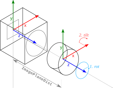
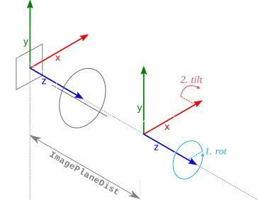
Figure 1. Tilt of the lens is described by the parameters
Rot,Tilt, andImagePlaneDist.
Rotdescribes the orientation of the tilt axis in relation to the x-axis of the sensor and has to be applied first.
Tiltdescribes the actual tilt of the lens.
ImagePlaneDistis the distance of the exit pupil of the lens to the image plane.These angles are typically roughly known based on the considerations that led to the use of the tilt lens or can be read off from the mechanism by which the lens is tilted.
-
Sx, Sy: Scale factors. They correspond to the horizontal and vertical distance between two neighboring cells on the sensor. As in most cases the image signal is sampled line-synchronously, Sy is determined by the dimension of the sensor and does not need to be estimated by the calibration process.
The initial values depend on the dimensions of the used chip of the camera. See the technical specification of your camera for the actual values.
Important
These values increase if the image is subsampled.
As projective cameras are described through the pinhole camera model, it is impossible to determine
Focus, Sx, and Sy simultaneously. Therefore, the algorithm will keep Sy fixed.For telecentric lenses, it is impossible to determine
Magnification, Sx, and Sy simultaneously. Therefore, the algorithm will keep Sy fixed.For image-side telecentric tilt lenses (see Tilt lenses and the Scheimpflug principle ), it is impossible to determine
Focus, Sx, Sy, and the tilt parameters tilt and rot simultaneously. Therefore, additionally to Sy, the algorithm will keep Sx fixed.For bilateral telecentric tilt lenses, it is impossible to determine
Magnification, Sx, Sy, and the tilt parameters tilt and rot simultaneously. Therefore, additionally to Sy, the algorithm will keep Sx fixed. -
Cx, Cy: Column (Cx) and row (Cy) coordinate of the principal point of the image (center of the radial distortion).
Use the half image width and height as initial values.
Important
These values decrease if the image is subsampled.
-
ImageWidth, Image Height: Width and height of the sampled image.
Important
These values decrease if the image is subsampled.
-
Line scan cameras
Line scan cameras have 12 or 16 internal parameters depending on the camera type.
For reasons explained below, parameters that are marked with an “*” (asterisk) are fixed and not estimated by the algorithm.
- Line scan cameras with regular lenses
-
Projective line scan cameras with regular lenses
-
-
'line_scan_division':
['line_scan_division', Focus, Kappa, Sx*, Sy*, Cx, Cy, ImageWidth, ImageHeight, Vx, Vy, Vz] -
'line_scan_polynomial':
['line_scan_polynomial', Focus, K1, K2, K3, P1, P2, Sx*, Sy*, Cx, Cy, ImageWidth, ImageHeight, Vx, Vy, Vz]
-
-
Telecentric line scan cameras with regular lenses
-
'line_scan_telecentric_division':
['line_scan_telecentric_division', Magnification, Kappa, Sx*, Sy*, Cx, Cy, ImageWidth, ImageHeight, Vx, Vy, Vz*] -
'line_scan_telecentric_polynomial':
['line_scan_telecentric_polynomial', Magnification, K1, K2, K3, P1, P2, Sx*, Sy*, Cx, Cy, ImageWidth, ImageHeight, Vx, Vy, Vz*]
-
- Description of the internal camera parameters of line scan cameras
-
-
CameraType: Type of the camera, as listed above.
-
Focus: Focal length of the lens (only for lenses that perform a perspective projection on the object side of the lens).
The initial value is the nominal focal length of the used lens, for example, 0.008 m.
-
Magnification: Magnification of the lens (only for lenses that perform a telecentric projection on the object side of the lens).
The initial value is the nominal magnification of the used telecentric lens (the image size divided by the object size), for example, 0.2.
-
Kappa (κ): Distortion coefficient of the division model to model the radial lens distortions.
Use 0.0 m-2 as initial value.
-
K1, K2, K3, P1, P2: Distortion coefficients to model the radial (K1, K2, K3) and decentering (P1, P2) lens distortions (only for the polynomial model).
Use 0.0 as initial value for all five coefficients.
-
Sx: Scale factor. Corresponds to the horizontal distance between two neighboring cells on the sensor.
FocusorMagnification, respectively, and Sx cannot be determined simultaneously. Therefore, Sx is kept fixed in the calibration. The initial value for Sx can be taken from the technical specifications of the camera.Important
This value increases if the image is subsampled.
-
Sy: Scale factor. During the calibration, it appears only in the form \(p_{v} = -S_{y} \cdot C_{y}\). Consequently, \(S_y\) and \(C_y\) cannot be determined simultaneously. Therefore, \(S_y\) is kept fixed in the calibration. \(p_{v}\) describes the distance of the image center point from the sensor line in meters. The initial value for \(S_y\) can be taken from the technical specifications of the camera.
Important
This value increases if the image is subsampled.
-
Cx: Column coordinate of the image center point (center of the radial distortions). Use half of the image width as the initial value for Cx.
Important
This value decreases if the image is subsampled.
-
Cy: Distance of the image center point (center of the radial distortions) from the sensor line in scanlines. The initial value can normally be set to 0.
-
ImageWidth, ImageHeight: Width and height of the sampled image.
Important
These values decrease if the image is subsampled.
-
Vx, Vy, Vz: X-, Y-, and Z-component of the motion vector.
The initial values for the x-, y-, and z-component of the motion vector depend on the image acquisition setup. Assuming a camera that looks perpendicularly onto a conveyor belt and that is rotated around its optical axis such that the sensor line is perpendicular to the conveyor belt (i.e., the y-axis of the camera coordinate system is parallel to the conveyor belt), use the initial values \(V_{x} = V_{z} = 0\). The initial value for \(V_{y}\) can then be determined, for example, from a line scan image of an object with known size (for example, calibration plate, ruler):
\[\begin{eqnarray*} V_{y} = \frac{l\,[m]}{l\,[row]} \end{eqnarray*}\]where
\[\begin{eqnarray*} l\,[m] & = & \mbox{Length of the object in object coordinates [meter]} \\ l\,[row] & = & \mbox{Length of the object in image coordinates [rows]} \end{eqnarray*}\]Example
If, compared to the above setup, the camera is rotated 30 degrees around its optical axis, i.e., around the z-axis of the camera coordinate system, the above determined initial values must be changed as follows:
\[\begin{eqnarray*} V^{z}_{x} & = & \sin(30^\circ) V_{y} \\ V^{z}_{y} & = & \cos(30^\circ) V_{y} \\ V^{z}_{z} & = & V_{z} = 0 \end{eqnarray*}\]If, compared to the first setup, the camera is rotated −20 degrees around the x-axis of the camera coordinate system, the following initial values result:
\[\begin{eqnarray*} V^{x}_{x} & = & V_{x} = 0 \\ V^{x}_{y} & = & \cos(-20^\circ) V_{y} \\ V^{x}_{z} & = & \sin(-20^\circ) V_{y} \end{eqnarray*}\]The quality of the initial values for \(V_{x}\), \(V_{y}\), and \(V_{z}\) are crucial for the success of the whole calibration. If they are not precise enough, the calibration may fail.
For telecentric line scan cameras, the value of \(V_{z}\) has no influence on the image position of 3D points and therefore cannot be determined. Consequently, \(V_{z}\) is not optimized and left at its initial value for telecentric line scan cameras. Therefore, the initial value of \(V_{z}\) should be set to
0.
For setups with multiple telecentric line scan cameras that share a common motion vector (for a detailed explanation, see Multi-view calibration), \(V_{z}\) can be determined based on the camera poses. Therefore, in this case \(V_{z}\) is optimized.
-
Restrictions for internal camera parameters
Note
The term focal length is not quite correct and would be appropriate only for an infinite object distance. To simplify matters, always the term focal length is used, even if the image distance is meant.
For all operators that use camera parameters as input, the respective parameter values are checked as to whether they fulfill the following restrictions:
For some operators, the restrictions differ slightly. In particular, for operators that do not support line scan cameras the following restriction applies:
External camera parameters🔗
The six external camera parameters describe the 3D pose, i.e., the position and orientation of the world coordinate system relative to the camera coordinate system.
External camera parameters
The x- and y-axis of the camera coordinate system are parallel to the column and row axes of the image, while the z-axis is perpendicular to the image plane. For line scan cameras, the pose of the world coordinate system refers to the camera coordinate system of the first image line.
-
TransX: Translation along the x-axis of the camera coordinate system
-
TransY: Translation along the y-axis of the camera coordinate system
-
TransZ: Translation along the z-axis of the camera coordinate system
-
RotX: Rotation around the x-axis of the camera coordinate system
-
RotY: Rotation around the y-axis of the camera coordinate system
-
RotZ: Rotation around the z-axis of the camera coordinate system
The pose tuple contains one more element, which is the representation type of the pose.
It codes the combination of the parameters OrderOfTransform, OrderOfRotation, and ViewOfTransform.
For more information about 3D poses, see create_pose.
When using a standard HALCON calibration plate, the world coordinate system is defined by the coordinate system of the calibration plate. For more information, see Calibration object above.
If a HALCON calibration plate is used, you can use the operator find_calib_object to determine initial values for all parameters.
Using HALCON calibration plates with rectangularly arranged marks, a combination of the two operators find_caltab and find_marks_and_pose will have the same effect.
Parameter units🔗
HALCON calibration plates use meters as unit. The camera parameters use corresponding units.
Parameter units
Table 1 lists the HALCON default units for the different camera parameters:
| Parameter | Unit | |
|---|---|---|
| External | RotX, RotY, RotZ |
deg, deg, deg |
TransX, TransY, TransZ |
m, m, m | |
| Internal | Cx, Cy |
px, px |
Focus |
m | |
ImagePlaneDist |
m | |
ImageWidth, ImageHeight |
px, px | |
K1, K2, K3 |
m-2, m-4, m-6 | |
Kappa (κ) |
m-2 | |
P1, P2 |
m-1, m-1 | |
Magnification |
– (scalar) | |
Sx, Sy |
m/px, m/px | |
Tilt, Rot |
deg, deg | |
Vx, Vy, Vz |
m / scanline, m / scanline, m / scanline |
Calibration can also be done using different units, but in this case, the related parameters have to be adapted.