Line scan cameras🔗
A line scan camera has only a one-dimensional line of sensor elements, that is, to acquire an image, the camera must move relative to the object (see []{#fig-camera_model-line_scan-principle}). This means that the camera moves over a fixed object, the object travels in front of a fixed camera, or camera and object are both moving.
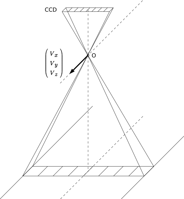
\(O\): Optical center
\((V_x,V_y,V_z)^T\): Motion vector
CCD: CCD sensor line
The relative motion between the camera and the object is modeled in HALCON as part of the internal camera parameters. In HALCON, the following assumptions for this motion are made:
-
the camera moves — relative to the object — with constant velocity along a straight line
-
the orientation of the camera is constant with respect to the object
-
the motion is equal for all images
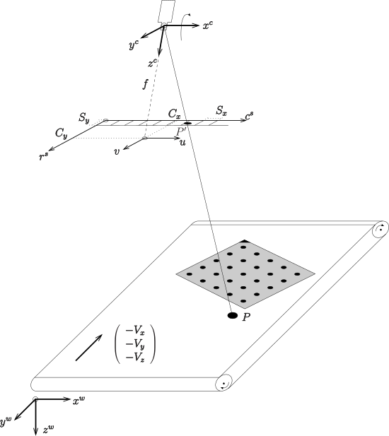
The motion is described by the motion vector \(V = (V_x,V_y,V_z)^T\), which must be given in [meters/scanline] in the camera coordinate system. The motion vector describes the motion of the camera, that is, it assumes a fixed object. In fact, this is equivalent to the assumption of a fixed camera with the object traveling along \(-V\).
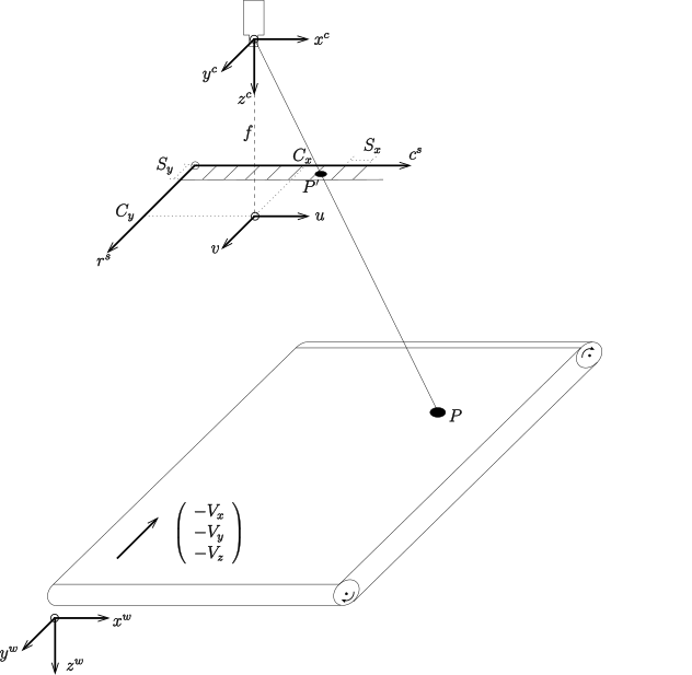
\((x^c, y^c, z^c)\): Camera coordinate system
\((r^s, c^s)\): Sensor line coordinate system
\((u, v)\): Image plane coordinate system
\((x^w, y^w, z^w)\): World coordinate system
HALCON supports a pinhole camera model as well as a telecentric camera model for line scan cameras.
The camera coordinate system of pinhole line scan cameras is defined as follows (see Figure 2): The origin of the coordinate system is the center of projection. The z-axis is identical to the optical axis and it is directed so that the visible points have positive z coordinates. The y-axis is perpendicular to the sensor line and to the z-axis. It is directed so that the motion vector has a positive y-component, that is, if a fixed object is assumed, the y-axis points in the direction in which the camera is moving. The x-axis is perpendicular to the y- and z-axis, so that the x-, y-, and z-axis form a right-handed coordinate system. For telecentric line scan cameras, the conventions are identical except for the origin of the coordinate system: it is given by the center of distortion for telecentric line scan cameras.
Similarly to area scan cameras, the projection of a point given in world coordinates into the image is modeled in two steps: First, the point is transformed into the camera coordinate system. Then, it is projected into the image.
As the camera moves over the object during the image acquisition, also the camera coordinate system moves relative to the object, that is, each image line has been imaged from a different position. This means that there would be an individual pose for each image line. To make things easier, in HALCON all transformations from world coordinates into camera coordinates and vice versa are based on the pose of the first image line only. The motion \(V\) is taken into account during the projection of the point \(p^c\) into the image.
The transformation from the WCS to the CCS of the first image line is a rigid transformation, which can be expressed by a pose or, equivalently, by the homogeneous transformation matrix \(\mvHomMatrixVar{c}{w}\). Therefore, the camera coordinates \(p^c = (x^c, y^c, z^c)\) of point \(P\) can be calculated from its world coordinates \(p^w = (x^w, y^w, z^w)\) simply by
The six parameters of this transformation (the three translations \(t_x\), \(t_y\), and \(t_z\) and the three rotations \(\alpha\), \(\beta\), and \(\gamma\)) are called the external camera parameters because they determine the position of the camera with respect to the world. In HALCON, they are stored as a pose, that is, together with a code that describes the order of translation and rotations.
For pinhole line scan cameras, the projection of the point \(p^c\) that is given in the camera coordinate system of the first image line into a (sub-)pixel [r,c] in the image is defined as follows:
Assuming
the following set of equations must be solved for \(\lambda\), \(\tilde{u}\), and \(t\):
where \(p_v = - S_y \cdot C_y\). \(u(\tilde{u},\tilde{v})\) and \(v(\tilde{u},\tilde{v})\) are depending on whether the division model or the polynomial model is used.
For telecentric line scan cameras, the projection of the point \(p^c\) into a (sub-)pixel [r,c] in the image is achieved by solving the following set of equations for \(\tilde{u}\) and \(t\):
where \(m\) denotes the magnification of the lens and \(p_v\), \(u(\tilde{u},\tilde{v})\), and \(v(\tilde{u},\tilde{v})\) are defined as above. Note that neither \(z\) nor \(V_z\) influence the projection for telecentric cameras.
The above formulas already include the compensation for radial distortions.
Finally, the point is transformed into the image coordinate system, that is, the pixel coordinate system:
\(S_x\) and \(S_y\) are scaling factors. \(S_x\) represents the distance of the sensor elements on the CCD line, \(S_y\) is the extent of the sensor elements in y-direction. The point \((C_x,C_y)^T\) is the principal point. Note that in contrast to area scan images, \((C_x,C_y)^T\) does not define the position of the principal point in image coordinates. It rather describes the relative position of the principal point with respect to the sensor line.
The parameters \(f, m, \kappa, K_1, K_2, K_3, P_1, P_2, S_x, S_y, C_x, C_y, V_x, V_y, V_z\) are called the internal camera parameters because they determine the projection from 3D to 2D performed by the camera.
As for area scan cameras, the calibration of a line scan camera is the process of determining the internal camera parameters and the external camera parameters \(t_x, t_y, t_z, \alpha, \beta, \gamma\) of the first image line.
Tips for line scan cameras🔗
In the following, some hints for the determination of the initial values for the internal camera parameters of a line scan camera are given:
- Focus f:
- The initial value for the focal length (only for pinhole lenses) is the nominal focal length of the used lens, for example, \(0.035\,m\).
- Magnification m:
- The initial value for the magnification (only for telecentric lenses) is the nominal magnification of the used lens, for example, 0.2.
- Kappa (\(\kappa\)):
- Use 0.0 as initial value (only for the division model).
- Or:
- K1, K2, K3, P1, P2:
-
Use the initial value 0.0 for each of the five coefficients (only for the polynomial model). Note that the parameters P1 and P2 are highly correlated with other parameters in the camera model. Therefore, they typically cannot be determined reliably and should be excluded from the calibration by calling
set_calib_data (CalibDataID, 'camera', 'general', 'excluded_settings', 'poly_tan_2') - Sx:
- The horizontal distance between two neighboring sensor elements can be taken from the technical specifications of the camera. Typical initial values are \(7\cdot10^{-6}\,m\), \(10\cdot10^{-6}\,m\), and \(14\cdot10^{-6}\,m\). Note: The value of Sx increases if the image is subsampled. Note also that Sx will not be calibrated for line scan cameras because Sx and Focus (for pinhole lenses) and Sx and Magnification (for telecentric lenses) cannot be determined simultaneously for line scan cameras.
- Sy:
- The size of a cell in the direction perpendicular to the sensor line can also be taken from the technical specifications of the camera. Typical initial values are \(7\cdot10^{-6}\,m\), \(10\cdot10^{-6}\,m\), and \(14\cdot10^{-6}\,m\). Note: The value of Sy increases if the image is subsampled. Note also that Sy will not be calibrated for line scan cameras because it cannot be determined separately from the parameter Cy.
- Cx:
-
The initial value for the x-coordinate of the principal point is half the image width. Note: The values of Cx decrease if the image is subsampled! Appropriate initial values are:
Image width Cx 1024 512 2048 1024 4096 2048 8192 4096 - Cy:
- Normally, the initial value for the y-coordinate of the principal point can be set to 0.
- ImageWidth and ImageHeight:
- These two parameters are determined by the used frame grabber and therefore are not calibrated.
- Vx, Vy, Vz:
-
The initial values for the x-, y-, and z-component of the motion vector depend on the image acquisition setup. Assuming a fixed camera that looks perpendicularly onto a conveyor belt, such that the y-axis of the camera coordinate system is anti-parallel to the moving direction of the conveyor belt (see Figure 3), the initial values are Vx = Vz = 0. The initial value for Vy can then be determined, for example, from a line scan image of an object with known size (for example, calibration plate or ruler): $$ V_y = L[m]/L[row] $$ with \(L[m]=\) Length of the object in object coordinates [meter] and \(L[row]=\) Length of the object in image coordinates [rows]. If, compared to the above setup, the camera is rotated 30 degrees around its optical axis, i.e., around the z-axis of the camera coordinate system (Figure 4), the above determined initial values must be changed as follows:
\[ \begin{aligned} V_{zx} &= \sin(30°) \cdot V_y \\ V_{zy} &= \cos(30°) \cdot V_y \\ V_{zz} &= V_z = 0 \end{aligned} \]If, compared to the first setup, the camera is rotated -20 degrees around the x-axis of the camera coordinate system (Figure 5), the following initial values result:
\[ \begin{aligned} V_{xx} &= V_x = 0 \\ V_{xy} &= \cos(-20°) \cdot V_y \\ V_{xz} &= \sin(-20°) \cdot V_y \end{aligned} \]The quality of the initial values for Vx, Vy, and Vz are crucial for the success of the whole calibration. If they are not accurate enough, the calibration may fail. Note that for telecentric line scan cameras, the value of \(V_z\) has no influence on the image position of 3D points and therefore cannot be determined. Consequently, \(V_z\) is not optimized and left at its initial value for telecentric line scan cameras. Therefore, the initial value of \(V_z\) should be set to 0.
Line scan setup scenarios
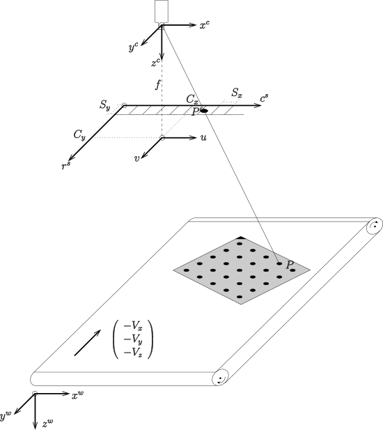
\((x^c, y^c, z^c)\): Camera coordinate system
\((r^s, c^s)\): Sensor line coordinate system
\((u, v)\): Image plane coordinate system
\((x^w, y^w, z^w)\): World coordinate system
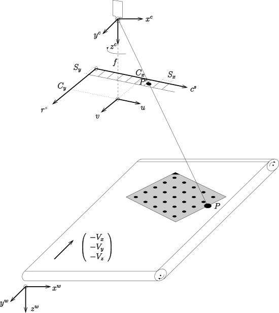
\((x^c, y^c, z^c)\): Camera coordinate system
\((r^s, c^s)\): Sensor line coordinate system
\((u, v)\): Image plane coordinate system
\((x^w, y^w, z^w)\): World coordinate system
\((x^c, y^c, z^c)\): Camera coordinate system
\((r^s, c^s)\): Sensor line coordinate system
\((u, v)\): Image plane coordinate system
\((x^w, y^w, z^w)\): World coordinate system
Troubleshooting for line scan camera calibration🔗
In general, the procedure for the calibration of line scan cameras is identical to the one for the calibration of area scan cameras.
However, line scan imaging suffers from a high degree of parameter correlation. For example, for pinhole line scan cameras, any small rotation of the linear array around the x-axis of the camera coordinate system can be compensated by changing the y-component of the translation vector of the respective pose. Even the focal length is correlated with the z-component of the translation vector of the pose, i.e., with the distance of the object from the camera.
The consequences of these correlations for the calibration of line scan cameras are that some parameters cannot be determined with high absolute accuracy. Nevertheless, the set of parameters is determined consistently, what means that the world coordinates can be measured with high accuracy.
Another consequence of the parameter correlations is that the calibration may fail in some cases where the start values for the internal camera parameters are not accurate enough.
If this happens, try the following approach for pinhole line scan cameras:
In many cases, the start values for the motion vector are the most difficult to set.
To achieve better start values for the parameters Vx, Vy, and Vz, reduce the number of parameters to be estimated such that the camera calibration succeeds.
-
Try to estimate the parameters
Vx,Vy,Vz,alpha,beta,gamma,tx,ty, andtzby callingset_calib_datawithItemType=camera,ItemIdx=general,DataName=calib_settings, andDataValue=['vx', 'vy', 'vz', 'alpha', 'beta', 'gamma', 'transx', 'transy', 'transz']if this does not work, tryDataValue=['vx', 'vy', 'vz', 'transx', 'transy', 'transz']. -
Determine the whole set of parameters using the above determined values for
Vx,Vy, andVzas start values. A similar approach may be used for telecentric line scan cameras. AstzandVzhave no effect for telecentric line scan cameras, these parameters do not need to be excluded explicitly. -
If none of the above proposed tips works, try to determine better start values directly from the camera setup. If possible, change the setup such that it is easier to determine appropriate start values, e.g., mount the camera such that it looks approximately perpendicularly onto the conveyor belt.
If the calibration plates lie in a plane, you may get the error 8440 (“Camera calibration did not converge”), because in this case the parameters are even more correlated.
A possible solution may be to exclude the rotation around the x axis, i.e., alpha from the calibration with the operator set_calib_data.