Area scan cameras🔗
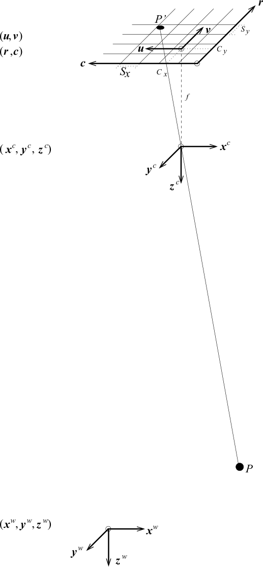
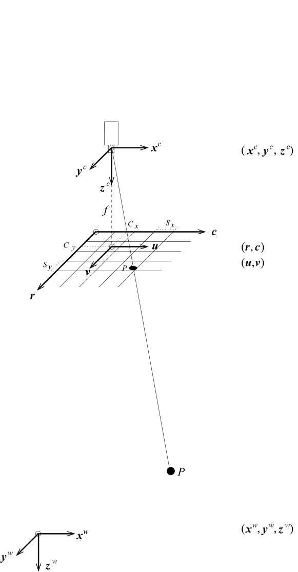
displays the perspective projection effected by a pinhole camera graphically. The world point \(P\) is projected through the optical center of the lens to the point \(P'\) in the image plane, which is located at a distance of \(f\) (the focal length) behind the optical center. Actually, the term “focal length” is not quite correct and would be appropriate only for an infinite object distance. To simplify matters, in the following always the term “focal length” is used even if the “image distance” is meant. Note that the focal length and thus the focus must not be changed after applying the camera calibration.
 |
 |
|
|---|---|---|
Camera coordinate system \((x^c, y^c, z^c)\)
World coordinate system \((x^w, y^w, z^w)\)
Image plane coordinate system \((u, v)\)
Image coordinate system \((r ,c)\)
Although the image plane in reality lies behind the optical center of the lens, it is easier to pretend that it lies at a distance of \(f\) in front of the optical center, as shown in . This causes the image coordinate system to be aligned with the pixel coordinate system (row coordinates increase downward and column coordinates to the right) and simplifies most calculations.
Transforming into camera coordinates (external camera parameters)🔗
With this, we are now ready to describe the projection of objects in 3D world coordinates to the 2D image plane and the corresponding camera parameters. First, we should note that the points \(P\) are given in a world coordinate system (WCS). To make the projection into the image plane possible, they need to be transformed into the camera coordinate system (CCS). The CCS is defined so that its \(x\) and \(y\) axes are parallel to the column and row axes of the image, respectively, and the \(z\) axis is perpendicular to the image plane.
The transformation from the WCS to the CCS is a rigid transformation, which can be expressed by a pose or, equivalently, by the homogeneous transformation matrix \(\mvHomMatrixVar{c}{w}\). Therefore, the camera coordinates \(p^c = (x^c, y^c, z^c)^T\) of point \(P\) can be calculated from its world coordinates \(p^w = (x^w, y^w, z^w)^T\) simply by
The six parameters of this transformation (the three translations \(t_x\), \(t_y\), and \(t_z\) and the three rotations \(\alpha\), \(\beta\), and \(\gamma\)) are called the external camera parameters because they determine the position of the camera with respect to the world. In HALCON, they are stored as a pose, that is, together with a code that describes the order of translation and rotations.
Projection🔗
The next step is the projection of the 3D point given in the CCS into the image plane coordinate system (IPCS). For the pinhole camera model, the projection is a perspective projection, which is given by
For cameras with hypercentric lenses, the following equation holds instead:
For the telecentric camera model, the projection is a parallel projection, which is given by
where \(m\) = magnification. As can be seen, the distance \(z\) of the object to the camera has no influence on the image coordinates.
Lens distortion🔗
After the projection into the image plane, the lens distortion modifies the coordinates \((u,v)^T\) of \(q^c\) to \(c {\tilde{q}^c} = (\tilde{u},\tilde{v})^T\). The effect is illustrated in Figure 1: If no lens distortion were present, the projected point \(P'\) would lie on a straight line from \(P\) through the optical center, indicated by the dotted line in Figure 1. Lens distortions cause the point \(P'\) to lie at a different position.
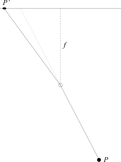
The lens distortion is a transformation that can be modeled in the image plane alone, that is, 3D information is unnecessary. In HALCON, the distortions can be modeled either by the division model or by the polynomial model.
The division model uses one parameter (\(\kappa\)) to model the radial distortions. The following equations transform the distorted image plane coordinates into undistorted image plane coordinates if the division model is used:
These equations can be inverted analytically, which leads to the following equations that transform undistorted coordinates into distorted coordinates if the division model is used:
 |
 |
 |
|---|---|---|
The parameter \(\kappa\) models the magnitude of the radial distortions. If \(\kappa\) is positive, the distortion is pincushion-shaped ( ), while for negative \(\kappa\) it is barrel-shaped ( ).
 |
 |
 |
|---|---|---|
 |
 |
 |
Effect of distortions modeled with the polynomial model with different values for the parameters \(K_1\), \(K_2\), \(K_3\), \(P_1\), and \(P_2\).
| \(K_1\) | \(K_2\) | \(K_3\) | \(P_1\) | \(P_2\) | |
|---|---|---|---|---|---|
| <0 | 0 | 0 | 0 | 0 | |
| <0 | > 0 | 0 | 0 | 0 | |
| <0 | > 0 | < 0 | 0 | 0 | |
| <0 | 0 | 0 | < 0 | 0 | |
| <0 | 0 | 0 | < 0 | > 0 | |
| <0 | > 0 | < 0 | < 0 | > 0 |
The polynomial model uses three parameters (\(K_{1}, K_{2}, K_{3}\)) to model the radial distortions, and two parameters (\(P_{1}, P_{2}\)) to model the decentering distortions. The following equations transform the distorted image plane coordinates into undistorted image plane coordinates if the polynomial model is used:
with \(r = \sqrt{\tilde{u}^2 + \tilde{v}^2}\). These equations cannot be inverted analytically. Therefore, distorted image plane coordinates must be calculated from undistorted image plane coordinates numerically.
Some examples for the kind of distortions that can be modeled with the polynomial model are shown in - .
Tilt lenses🔗
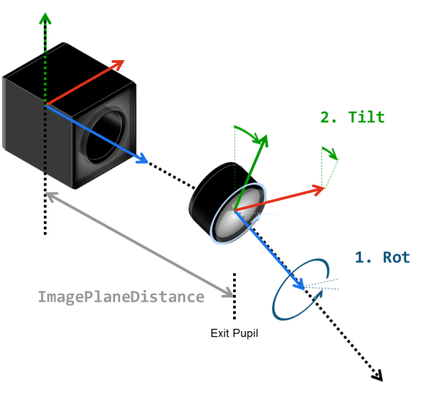
Tilt and Rot. Rot describes the orientation of the tilt axis. Tilt describes the actual tilt of the lens. If the lens is a tilt lens, the tilt of the lens with respect to the image plane is described by two parameters: The rotation angle \(\rho\) \((0^\circ \le \rho < 360^\circ)\), which describes the direction of the tilt axis, and the tilt angle \(\tau (0^\circ \le \tau < 90^\circ)\), by which the sensor plane is tilted with respect to the optical axis (see Figure 2).
For tilt lenses, different camera models are available, as they can have different geometries. Note further that different results are obtained with different angles of incidence.
| Ray geometry | Lens type | Internal camera parameters |
|---|---|---|
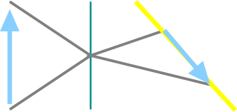 |
projective tilt lens | area_scan_tilt_* |
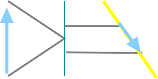 |
image-side telecentric tilt lens | area_scan_tilt_image_side_telecentric_* |
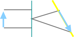 |
object−side telecentric tilt lens | area_scan_tilt_object_side_telecentric_* |
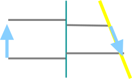 |
bilateral telecentric tilt lens | area_scan_tilt_bilateral_telecentric_* |
For projective tilt lenses and object-side telecentric tilt lenses, the projection of \(c {\tilde{q}} = (\tilde{u},\tilde{v})^T\) into the point \(t q = (\hat{u},\hat{v})^T\), which lies in the tilted image plane, is described by a projective 2D transformation, that is, by the homogeneous matrix $$:
where
with \(d = ImagePlaneDist\) and
with \(\textit{Rot} = \rho\) and \(\textit{Tilt} = \tau\).
For image-side telecentric tilt lenses and bilateral telecentric tilt lenses, the projection onto the tilted image plane is described by a linear 2D transformation, that is, by a \(2 \times 2\) matrix:
where \(Q\) is defined as above for projective lenses.
Transforming into pixel coordinates🔗
Finally, the point \(q^c = (\tilde{u},\tilde{v})^T\) (or \(q^t\) if a tilt lens is present) is transformed from the image plane coordinate system into the image coordinate system (the pixel coordinate system):
Here, \(S_x\) and \(S_y\) are scaling factors. For pinhole cameras, they represent the horizontal and vertical distance of the sensors elements on the CCD chip of the camera. For cameras with telecentric lenses, they represent the size of a pixel in world coordinates (not taking into account the lens distortions). The point \((C_x,C_y)^T\) is the principal point of the image. For pinhole cameras, this is the perpendicular projection of the optical center onto the image plane, that is, the point in the image from which a ray through the optical center is perpendicular to the image plane. It also defines the center of the radial distortions. For telecentric cameras, no optical center exists. Therefore, the principal point is solely defined by the radial distortions.
The parameters \(f,\textit{Magnification},\kappa,K_{1},K_{2},K_{3},P_{1},P_{2},\tau,\rho,S_x,S_y,C_x,C_y\) are called the internal camera parameters because they determine the projection from 3D to 2D performed by the camera.
Note that in addition, the CameraType, the ImageWidth, the ImageHeight and, only for object-side telecentric tilt lenses, the ImagePlaneDist must be given.
Depending on the camera type, lens type, and lens distortion model, only a subset of the parameters is actually used.
To create camera parameter tuples, you can use the different procedures available in HALCON.
There is a procedure available for each camera type, for example, gen_cam_par_area_scan_division.
We can see that camera calibration is the process of determining the internal camera parameter and the external camera parameters \((t_x,t_y,t_z,\alpha,\beta,\gamma)\).
Tips for area scan cameras🔗
If you face problems using a camera model and you suspect that the sensor of your camera may be tilted (for example, due to a defect), we suggest to check if a calibration using a camera model for object-side telecentric tilt lenses ('area_scan_tilt_object_side_telecentric_division' or 'area_scan_tilt_object_side_telecentric_polynomial') leads to better results.
In the following, some hints for the determination of the initial values for the internal camera parameters of an area scan camera are given:
- Focal length of the lens (only for lenses that perform a perspective projection on the object side of the lens). The initial value is the nominal focal length of the used lens, for example, \(0.008\,m\).
- Magnification of the lens (only for lenses that perform a telecentric projection on the object side of the lens). The initial value is the nominal magnification of the used telecentric lens (the image size divided by the object size), for example, 0.2.
- Use 0.0 as initial value (only for the division model).
- Alternatively to 0.0 as initial value for \(\kappa\), use the initial value 0.0 for each of the five coefficients (only for the polynomial model).
- Distance of the tilted image plane from the perspective projection center (only tilt lenses that perform a perspective projection on the image side of the lens), for example, \(0.02\,m\). The initial value is the distance of the exit pupil of the lens to the image plane. The exit pupil is the (virtual) image of the aperture stop (typically the diaphragm), as viewed from the image side of the lens. Typical values are in the order of a few centimeters to very large values if the lens is close to being image-side telecentric.
- The tilt angle \(\tau\) \((0^\circ \le \tau \le 90^\circ)\) describes the angle by which the optical axis is tilted with respect to the normal of the sensor plane. The rotation angle \(\rho\) \((0^\circ \le \rho < 360^\circ)\) describes the direction in which the optical axis is tilted. These parameters are only used if a tilt lens is part of the camera setup. These angles are typically roughly known based on the considerations that led to the use of the tilt lens or can be read off from the mechanism by which the lens is tilted.
-
Scale factors. This corresponds to the horizontal and vertical distance between two neighboring cells on the sensor. Since in most cases the image signal is sampled line-synchronously, \(S_{y}\) is determined by the dimension of the sensor and does not need to be estimated by the calibration process. The initial values depend on the dimensions of the used chip of the camera. See the technical specification of your camera for the actual values.
Attention: These values increase if the image is subsampled!
-
Initial values for the coordinates of the principal point are the coordinates of the image center, that is, half the image width and half the image height. Note: The values of Cx and Cy decrease if the image is subsampled! Appropriate initial values are, for example:
Full image (640 × 480) Subsampling (320 × 240) Cx 320.0 160.0 Cy 240.0 120.0 -
These two parameters are set by the used frame grabber and therefore are not calibrated. Appropriate initial values are, for example:
Full image (640 × 480) Subsampling (320 × 240) ImageWidth 640 320 ImageHeight 480 240
Focus f:
Magnification m:
Kappa (\(\kappa\)):
K1, K2, K3, P1, P2:
ImagePlaneDist:
Tilt and Rot:
Sx and Sy:
Cx and Cy:
ImageWidth and ImageHeight: