3D Gripping Point Detection🔗
3D Gripping Point Detection is a deep-learning-based approach to detect gripping points on arbitrary objects in a 3D scene. The results can be used to target the gripping points with a robot arm and pick up the objects using vacuum grippers with suction cups.
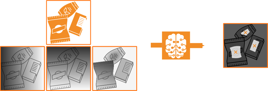
Figure 1. A possible example for a 3D Gripping Point Detection application: A 3D scene (for example, an RGB image and XYZ-images) is analyzed and possible gripping points are suggested.
HALCON provides a pretrained model, which is ready for inference without an additional training step. To finetune the model for a specific task, it is possible to retrain it on a custom application domain. 3D Gripping Point Detection also works on objects that were not seen in training. Thus, there is no need to provide a 3D model of the objects that are to be targeted. 3D Gripping Point Detection can also cope with scenes containing various different objects at once, scenes with partly occluded objects, and with scenes containing cluttered 3D data.
 |
 |
 |
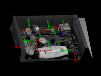 |
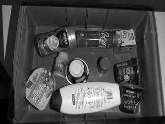
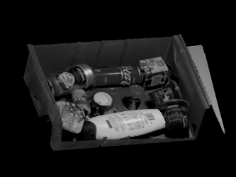
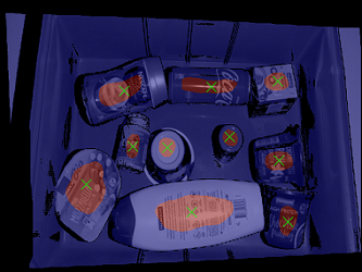
Figure 2.
2D input image (intensity image)
3D scene (generated from XYZ-images)
Visualization of estimated gripping points on the 2D input image
Visualization of estimated gripping points as poses in the 3D scene
About data🔗
This section gives information on the data that needs to be provided for the model inference or training and evaluation of a 3D Gripping Point Detection model.
As a basic concept, the model handles data by dictionaries, meaning it receives the input data from a dictionary DLSample and returns a dictionary DLResult.
For more information about data handling, see Deep learning > HALCON DL model.
3D scenes🔗
3D Gripping Point Detection processes 3D scenes, which consist of regular 2D images and depth information.
To adapt these 3D data to the network input requirements, a preprocessing step is necessary for the inference. For information about certain preprocessing parameters, see Specific preprocessing parameters below. To ensure the necessary data quality, using a high resolution 3D sensor is recommended.
The following data are needed:
2D image
-
RGB image, or
-
intensity (gray value) image
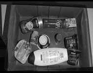
Figure 3. Intensity image
Depth information
-
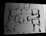
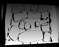
X-image (values need to increase from left to right)
-
Y-image (values need to increase from top to bottom)
-
Z-image (values need to increase from points close to the sensor to far points; this is for example the case if the data is given in the camera coordinate system)
 |
 |
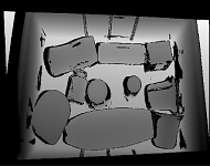 |
Figure 4. X-image, Y-image, Z-image
Normals (optional)
- 2D mappings (3-channel image)
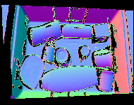
Figure 5. Normals image
Note
-
Providing normal images improves the runtime, as this avoids the need for their computation.
-
To restrict the search area, the domain of the RGB/intensity image can be reduced. For more information, see Specific preprocessing parameters below.
-
The domain of the XYZ-images and the (optional) normals images need to be identical. Furthermore, for all input data, only valid pixels may be part of the used domain.
Data for training and evaluation🔗
The training data is used to train and evaluate a network specifically for your application.
The dataset needed for this consists of 3D scenes and corresponding information on possible gripping surfaces given as segmentation images. They have to be provided in a way the model can process them. For information about the 3D scene requirements, see 3D scenes above.
How the data has to be formatted in HALCON for a DL model is explained in Deep learning > HALCON DL model.
In short, a dictionary DLDataset serves as a database for the information needed by the training and evaluation procedures.
The data for DLDataset can be read using read_dl_dataset_3d_gripping_point_detection.
See the reference of read_dl_dataset_3d_gripping_point_detection for information on the required contents of a 3D Gripping Point Detection DLDataset.
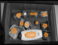
Along with 3D scenes, segmentation images need to be provided, which serve as the ground truth. The segmentation images contain two gray values that denote every pixel in the scene to be either a valid gripping point or not.
Tip
You can label your data using the MVTec Deep Learning Tool, available from the MVTec website.
 |
 |
Figure 6. Labeling of an intensity image. Segmentation image, denoting gripping points (gray)
Make sure that the whole labeled area provides robust gripping points for the robot. Consider the following aspects when labeling your data:
-
Gripping points need to be on a surface that can be accessed by the robot arm without being obstructed.
-
Gripping points need to be on a surface that the robot arm can grip with its suction cup. Therefore, consider the object’s material, shape, and surface tilt with regard to the ground plane.
-
Take the size of the robots suction cup into account.
-
Take the strength of the suction cup into account.
-
Tend to label gripping points near the object’s center of mass (especially for potentially heavier items).
-
Gripping points should not be at an object’s border.
-
Gripping points should not be at the border of visible object regions.
Model output🔗
As inference output, the model will return a dictionary DLResult for every sample.
This dictionary includes the following entries:
'gripping_map'- Binary image, indicating for each pixel of the scene whether the model predicted a gripping point (pixel value =
1.0) or not (0.0). 'gripping_confidence'- Image, containing raw, uncalibrated confidence values for every point in the scene.
Evaluation measures for 3D Gripping Point Detection results🔗
For 3D Gripping Point Detection, the following evaluation measures are supported in HALCON:
mean_pro- Mean overlap of all ground truth regions labeled as gripping class with the predictions (per-region overlap). See the paper referenced in the footnote for a detailed description of this evaluation measure.1
mean_precision-
Mean pixel-level precision of the predictions for the gripping class. The precision is the proportion of true positives to all positives (true (TP) and false (FP) ones).
\[ \textrm{precision} = \frac{\textrm{TP}}{\textrm{TP} + \textrm{FP}} \] mean_iou- Intersection over union (IoU) between the ground truth pixels and the predicted pixels of the gripping class. See Evaluation measures for the data from semantic segmentation for a detailed description of this evaluation measure.
gripping_point_precision- Proportion of true positives to all positives (true and false ones).
- For this measure, a true positive is a correctly predicted gripping point, meaning the predicted point is located within a ground truth region. However, only one gripping point per region is considered a true positive, additional predictions in the same region are considered false positives.
gripping_point_recall-
The recall is the proportion of the number of correctly predicted gripping points to the number of all ground truth regions of the gripping class.
\[ \textrm{recall} = \frac{\textrm{TP}}{\textrm{TP} + \textrm{FN}} \] gripping_point_f_score-
To represent precision and recall with a single number, we provide the F-score, the harmonic mean of precision and recall.
\[ \textrm{F-score} = 2 \times \frac{\textrm{precision} \times \textrm{recall}}{\textrm{precision} + \textrm{recall}} \]
Postprocessing🔗
The model results DLResult can be postprocessed with gen_dl_3d_gripping_points_and_poses to generate gripping points.
Furthermore, this procedure can be parameterized to reject small gripping regions using min_area_size, or serve as a template to define custom selection criteria.
The procedure adds the following entry to the dictionary DLResult:
-
Tuple of dictionaries containing information on suitable gripping points in a scene:
-
'region': Connected region of potential gripping points. The determined gripping point lies inside this region. -
'row': Row coordinate of the gripping point in the preprocessed RGB/intensity image. -
'column': Column coordinate of the gripping point in the preprocessed RGB/intensity image. -
'pose': 3D pose of the gripping point (relative to the coordinate system of the XYZ-images, i.e., of the camera), which can be used by the robot.
-
'image_width','image_height'- Determine the image dimensions of the images to be inferred.
- With larger image dimensions and thus a better resolution, smaller gripping surfaces can be detected. However, the runtime and memory consumption of the application increases.
'min_z','max_z'- Determine the allowed distance from the camera for 3D points based on the Z-image.
- These parameters can therefore help to reduce erroneous outliers and therefore increase the application robustness.
'gripping_points'
Specific preprocessing parameters🔗
In the preprocessing step, along with the data, preprocessing parameters need to be passed to preprocess_dl_samples.
Two pairs of those preprocessing parameters have particularly significant impact:
A restriction of the search area can be done by reducing the domain of the input images (using reduce_domain).
The way preprocess_dl_samples handles the domain is set using the preprocessing parameter 'domain_handling'.
The parameter 'domain_handling' should be used in a way that only essential information is passed on to the network for inference.
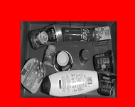
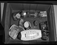
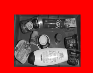
The following images show how an input image with reduced domain is passed on after the preprocessing step depending on the set 'domain_handling'.
 |
 |
 |
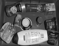 |
Figure 7.
Input image with reduced domain (red),
image for 'full_domain',
image for 'keep_domain',
image for 'crop_domain'
-
Bergmann, P., Batzner, K., Fauser, M., Sattlegger, D. and Steger, C., 2021. The MVTec anomaly detection dataset: a comprehensive real-world dataset for unsupervised anomaly detection. International Journal of Computer Vision, 129(4), pp.1038-1059. ↩