Mono 3D🔗
Determine the pose of a known 3D object using at least three corresponding points, i.e., points with known 3D object coordinates for which the corresponding image coordinates are extracted.
If the internal camera parameters are known, the pose of an object can be determined by a call of the operator vector_to_pose.
The individual steps are illustrated based on the example program %HALCONEXAMPLES%\solution_guide\
3d_vision\pose_of_known_3d_object.hdev, which determines the pose of a metal part with respect to a given world coordinate system.
First, the camera must be calibrated, that is, the internal camera parameters and, if the pose of the object is to be determined relative to a given world coordinate system, the external camera parameters must be determined.
The world coordinate system can either be identical to the calibration plate coordinate system belonging to the calibration plate from one of the calibration images, or it can be modified such that it fits to some given reference coordinate system (Figure 1).
This can be achieved, for example, by using the operator set_origin_pose.
set_origin_pose (PoseOfWCS, -0.0568, 0.0372, 0, PoseOfWCS)or if other transformations than translations are necessary, via homogeneous transformation matrices.
pose_to_hom_mat3d (PoseOfWCS, camHwcs)
hom_mat3d_rotate_local (camHwcs, rad(180), 'x', camHwcs)
hom_mat3d_to_pose (camHwcs, PoseOfWCS)
With the homogeneous transformation matrix \(\mvHomMatrixVar{c}{w}\), which corresponds to the pose of the world coordinate system, world coordinates can be transformed into camera coordinates.
Scheme: Determination of the pose of the world coordinate system.
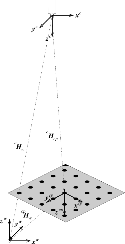
Camera coordinate system: \((x^c, y^c, z^c)\)
Calibration plate coordinate system: \((x^{cp}, y^{cp}, z^{cp})\)
World coordinate system: \((x^w, y^w, z^w)\)
Then, the pose of the object can be determined from at least three points (control points) for which both the 3D object coordinates and the 2D image coordinates are known.
The 3D coordinates of the control points need to be determined only once. They must be given in a coordinate system that is attached to the object. You should choose points that can be extracted easily and accurately from the images. The 3D coordinates of the control points are then stored in three tuples, one for the x coordinates, one for the y coordinates, and the last one for the z coordinates.
In each image from which the pose of the object should be determined, the control points must be extracted. This task depends heavily on the object and on the possible poses of the object. If it is known that the object will not be tilted with respect to the camera the detection can, for example, be carried out by shape-based matching .
Once the image coordinates of the control points are determined, they must be stored in two tuples that contain the row and the column coordinates, respectively. Note that the 2D image coordinates of the control points must be stored in the same order as the 3D coordinates.
In the example program, the centers of the three holes of the metal part are used as control points.
Their image coordinates are determined with the procedure determine_control_points.
procedure determine_control_points (Image: Intersections: : RowCenter, ColCenter)which is part of the example program %HALCONEXAMPLES%\solution_guide\3d_vision\pose_of_known_3d_object.hdev.
Now, we simply call the operator vector_to_pose, passing the 3D object coordinates and the 2D image coordinates of the control points together with the internal camera parameters.
Scheme: Transformation between object coordinates and world coordinates
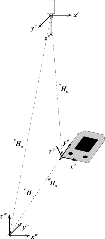
Camera coordinate system: \((x^c, y^c, z^c)\)
Calibration plate coordinate system: \((x^{cp}, y^{cp}, z^{cp})\)
World coordinate system: \((x^w, y^w, z^w)\)
vector_to_pose (ControlX, ControlY, ControlZ, RowCenter, ColCenter, CamParam, 'iterative', 'error', PoseOfObject, Errors)If both the pose of the world coordinate system and the pose of the object coordinate system are known with respect to the camera coordinate system (see Figure 2), it is easy to determine the transformation matrices for the transformation of object coordinates into world coordinates and vice versa:
where \(\mvHomMatrixVar{w}{o}\) is the homogeneous transformation matrix for the transformation of object coordinates into world coordinates and \(\mvHomMatrixVar{c}{w}\) and \(\mvHomMatrixVar{c}{o}\) are the homogeneous transformation matrices corresponding to the pose of the world coordinate system and the pose of the object coordinate system, respectively, each with respect to the camera coordinate system.
The transformation matrix for the transformation of world coordinates into object coordinates can be derived by:
The calculations described above can be implemented in HDevelop as follows. First, the homogeneous transformation matrices are derived from the respective poses.
pose_to_hom_mat3d (PoseOfWCS, camHwcs)
pose_to_hom_mat3d (PoseOfObject, camHobj)
Then, the transformation matrix for the transformation of object coordinates into world coordinates is derived.
hom_mat3d_invert (camHwcs, wcsHcam)
hom_mat3d_compose (wcsHcam, camHobj, wcsHobj)
Now, known object coordinates can be transformed into world coordinates with affine_trans_point_3d.
affine_trans_point_3d (wcsHobj, CornersXObj, CornersYObj, CornersZObj, CornersXWCS, CornersYWCS, CornersZWCS)In the example program %HALCONEXAMPLES%\solution_guide\3d_vision\
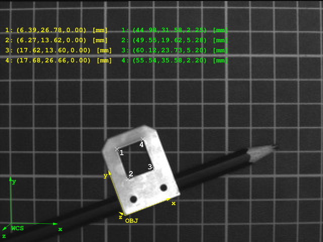
pose_of_known_3d_object.hdev, the world coordinates of the four corners of the rectangular hole of the metal part are determined from their respective object coordinates.
The object coordinate system and the world coordinate system are visualized as well as the respective coordinates for the four points (see Figure 3).