Workflow🔗
Select the model ROI🔗
As a first step of the perspective deformable matching, the region of interest that specifies the template image must be selected.
This region can have an arbitrary shape, that is, it can also contain holes or consist of several parts that are not connected. Thus, it is possible to create an ROI that contains only “robust” parts of the object.
The ROI must be selected so that it contains all prominent structures of the object and also some pixels outside of them, as their immediate surroundings (neighborhood) are needed to obtain the model.
Furthermore, you can speed up the later search using a subsampling. For that, the ROI should not be too “thin”, because otherwise it vanishes at higher pyramid levels! As a rule of thumb, you are on the safe side if an ROI is \(2^{NumLevels-1}\) pixels wide. That is, a width of 8 pixels allows to use 4 pyramid levels.
After having selected a suitable ROI, the reduced image is used as template image for the creation of the model.
Create a suitable perspective deformable model🔗
Having derived the template image from the reference image, the perspective deformable model can be created. Note that the perspective deformable matching consists of different methods to find the trained objects in images. Depending on the selected method, one of the following operators is used to create the model:
create_planar_uncalib_deformable_modelcreates a model for an uncalibrated perspective deformable matching that uses a template image to derive the model.create_planar_uncalib_deformable_model_xldcreates a model for an uncalibrated perspective deformable matching that uses XLD contours to derive the model. Note that after a first match, it is strongly recommended to determine the polarity information for the model withset_planar_uncalib_deformable_model_metric.create_planar_calib_deformable_modelcreates a model for a calibrated perspective deformable matching that uses a template image to derive the model.create_planar_calib_deformable_model_xldcreates a model for a calibrated perspective deformable matching that uses XLD contours to derive the model. Note that after a first match, it is strongly recommended to determine the polarity information for the model withset_planar_calib_deformable_model_metric.
When adjusting the parameters you can also let Halcon assist you:
- Use automatic parameter suggestion:
You can let Halcon suggest suitable values for many of these parameters by either setting the corresponding parameters to the value'auto'within the operator that is used to create the model or by applyingdetermine_deformable_model_paramsto automatically determine values for a perspective deformable model from a template image and then decide individually if you use the suggested values for the creation of the model.
Note that both approaches return only approximately the same values and the values that are returned by the operators that are used to create the model are more precise.
- Apply inspect_shape_model:
As the perspective deformable matching uses XLD contours to build the model, which is similar to shape-based matching, you can useinspect_shape_modelto try different values for the parametersNumLevelsandContrast. The operator returns the resulting representation of a shape model with multiple pyramid levels and thus allows you to visually check if the object of interest is represented adequately by the model.
If several combinations of parameter values do not lead to a satisfying representation of the object, maybe the template image, that is, the model’s ROI was not selected properly.
Note that after the creation of the model, the model can still be modified.
Specify pixels that are part of the model🔗
Affected parameters
Contrast
For the model those pixels are selected whose contrast, that is, gray value difference to neighboring pixels, exceeds a threshold specified by the parameter Contrast when calling create_planar_uncalib_deformable_model or create_planar_calib_deformable_model.
The parameter Contrast is similar to the corresponding parameter of shape-based matching.
The only difference is that here small structures are not suppressed within Contrast but with the separate generic parameter 'min_size' that is set via GenParamName and GenParamValue.
Speed up the search using subsampling and point reduction🔗
Affected parameters
NumLevels, Optimization
To speed up the matching process, subsampling can be used. An image pyramid is created, consisting of the original, full-sized image and a set of downsampled images. The model is then created and searched on the different pyramid levels.
You can specify how many pyramid levels are used via the parameter NumLevels.
A further reduction of model points can be enforced via the parameter Optimization.
This may be useful to speed up the matching in the case of particularly large models.
The functional principle of both parameters is similar to the parameters that are used for shape-based matching.
Allow a range of orientation and scale🔗
Affected parameters
AngelExtent, AngleStart, AngleStep, ScaleCMax, ScaleCMin, ScaleCStep, ScaleRMax, ScaleRMin, ScaleRStep
Note that AngleStart, AngleExtent, ScaleRMax, and ScaleCMax are not used by this operator.
Instead, they have to be specified within the operator find_planar_uncalib_deformable_model.
ScaleRMin and ScaleCMin can be relevant if you expect matches that are smaller than in the original image Template.
Then, if NumLevels is set to 'auto', the number of used pyramid levels may decrease.
The parameters AngleStep, ScaleRStep, and ScaleCStep can be determined automatically by setting their values to 'auto'.
Generally, this should lead to good results.
For more information about how these parameters work, please refer to the operator find_planar_uncalib_deformable_model.
Specify which pixels are compared with the model🔗
Affected parameters
Metric, MinContrast
The parameter MinContrast lets you specify which contrast a point in a search image must at least have in order to be compared with the model, whereas Metric lets you specify whether and how the polarity, that is, the direction of the contrast must be observed.
The parameters are similar to the corresponding parameters of shape-based matching.
The only difference is that for perspective deformable matching a further value for Metric is available that allows to observe the polarity in sub-parts of the model.
A sub-part is a set of model points that are adjacent.
For different calculations of the perspective deformable matching, the model is divided into a set of sub-parts that have approximately the same size.
When setting Metric to 'ignore_part_polarity', the different sub-parts may have different polarities as long as the polarities of the points within the individual sub-parts are the same.
This is helpful, for example, if due to the movement in the 3D space different reflections on the object are expected.
As these reflections typically are not too small, 'ignore_part_polarity' is a trade-off between 'ignore_global_polarity', which does not work with locally changing polarities, and 'ignore_local_polarity', which requires a very fine structured inspection and thus slows down the search significantly.
Adjust generic parameters🔗
Affected parameters
GenParamName, GenParamValue
Typically, there is no need to adjust the generic parameters that are set via GenParamName and GenParamValue.
But in rare cases, it might be helpful to adjust the splitting of the model into sub-parts, which are needed for different calculations of the perspective deformable matching, or to suppress small connected components of the model contours.
The size of the sub-parts is adjusted setting GenParamName to 'part_size' and GenParamValue to 'small', 'medium', or 'big'.
Small connected components of the model contours can be suppressed by setting GenParamName to 'min_size'.
The corresponding numeric value that is specified in GenParamValue describes the number of points a connected part of the object must at least contain to be considered for the following calculations.
The effect corresponds to the suppression of small structures that can be applied for shape-based matching within the parameter Contrast.
Specify the camera parameters and the reference pose🔗
Affected parameters
CamParam, ReferencePose
For the calibrated matching, the internal camera parameters (CamParam) and a reference pose (ReferencePose) have to be specified.
We recommend to obtain both using a camera calibration.
Other approaches for determining the pose of the object plane comprise a manual measurement of the extents of the model, which is rather intricate and often inaccurate, stereo vision (see Stereo system), or 3D laser triangulation, for example, using sheet of light (see Sheet of light).
Inspect and modify the perspective deformable model🔗
If you want to visually inspect an already created deformable model, you can use get_deformable_model_contours to get the XLD contours that represent the model in a specific pyramid level.
In case that the model was generated by create_planar_calib_deformable_model_xld, the contours by default are returned in the world coordinate system in metric units.
Here, the contours must be transformed by the returned pose for visualizing a match.
In all other cases, the contours of the model by default are returned in the image coordinate system in pixel units.
For the calibrated matching you can specify the coordinate system in which the contours are returned when calling get_deformable_model_contours with the operator set_deformable_model_param.
To inspect the current parameter values of a model, you query them with get_deformable_model_params.
This may be necessary if during the creation of the model an automatic parameter selection was used or if the model was created within another program, saved to file with write_deformable_model, and read from this file in the current program with read_deformable_model.
Additionally, you can query the coordinates of the origin of the model using get_deformable_model_origin.
After the creation of the model and before you search the object in a search image, you can further modify the model.
In particular, you can apply set_deformable_model_origin to change its point of reference and thus, in case of a calibrated matching, also its reference pose.
But similar to shape-based matching, when modifying the point of reference, the accuracy of the estimated position may decrease.
Important
If possible, the point of reference should not be changed. Instead, a suitable ROI for the model creation should be selected right from the start.
Modifying the point of reference
For the case that you nevertheless need to modify the point of reference, for example, if the origin should be placed on a specific part of the object, for example, a corner of the object or a drill hole, and you want to apply a calibrated matching, we here shortly describe the relation between the reference pose, the model pose, and an offset that is manually applied to the point of reference.
In particular, when creating the template model for a calibrated matching, the reference pose, which was obtained, for example, by a camera calibration, is automatically modified by an offset so that its origin corresponds to the projection of the center of gravity of a rectified version of the template image (that is, the ROI) onto the reference plane and the axes of the obtained model coordinate system are parallel to those of the initial reference pose (see Figure 1).
If you use set_deformable_model_origin to additionally apply an offset to the origin of the thus obtained model pose, the offset is set in image coordinates for the internally rectified template image.
To determine the necessary number of pixels for the row and column direction it is convenient to query the rectified contour of the object from the template model with get_deformable_model_contours.
After setting a manual offset, the obtained image point is automatically projected to the object plane as origin of the modified pose and the pose is adapted accordingly for all following operations.
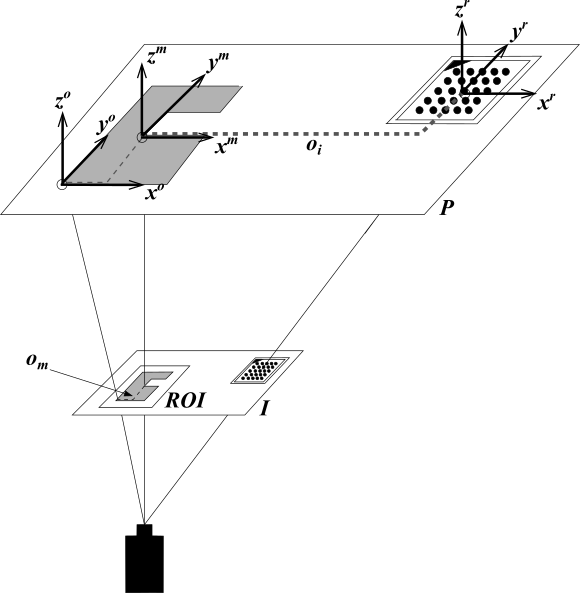
\(x^r y^r z^r\): reference pose
\(x^m y^m z^m\): model pose
\(x^o y^o z^o\): model pose with offset
\(I\): image
\(P\): object plane
\(o_m\): manual offset
\(o_i\): internal offset