Sheet of light🔗
Laser triangulation can be used to reconstruct the surface of a 3D object by approximating it via a set of height profiles. Halcon provides operators for a special type of laser triangulation that is called sheet-of-light technique.
The principle of sheet of light🔗
The basic idea of the sheet-of-light technique is to project a thin luminous straight line, e.g., generated by a laser line projector, onto the surface of the object that is to be reconstructed and then image the projected line with a camera. As shown in Figure 1 the projection of the laser line builds a plane that is called light plane or sheet of light. The optical axis of the camera and the light plane form an angle \(\alpha\), which is called angle of triangulation. The points of intersection between the laser line and the camera view depend on the height of the object. Thus, if the object onto which the laser line is projected differs in height, the line is not imaged as a straight line but represents a profile of the object. Using this profile, we can obtain the height differences of the object. To reconstruct the whole surface of an object, i.e., to get many height profiles, the object must be moved relative to the measurement system, i.e., the unit built by the laser line projector and the camera.
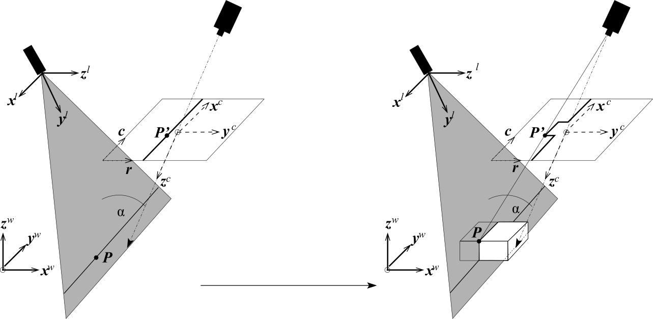
Camera coordinate system \((x^c, y^c, z^c)\)
Laser plane pose \((x^l, y^l, z^l)\)
World coordinate system \((x^w, y^w, z^w)\)
Image coordinate system \((r ,c)\)
Angle of triangulation \(\alpha\)
Point \(P\)
Projection of point \(P'\)
The sheet-of-light technique can be applied either to a calibrated measurement setup or to the uncalibrated setup.
If the setup is calibrated, the measurement returns the disparities, the x, y, and z coordinates of the points that build the profiles in the world coordinate system (WCS, see Figure 1), and a 3D object model that is derived from the x, y, and z coordinates.
The disparities are returned in form of a disparity image, i.e., the disparities of each measured profile are stored in one row of the disparity image (see Figure 2 and note that the camera must be oriented such that the profiles are roughly parallel to the rows of the image).
The x, y, and z coordinates are also not explicitly returned as values but are expressed as values of pixels within images.
That is, three images are returned, one for the x coordinates (X), one for the y coordinates (Y), and one for the z coordinates (Z).
The 3D object model contains information about the 3D coordinates and the corresponding 2D mapping.
If the setup is uncalibrated, only the disparity image and a score that describes how reliable the measurement result is can be returned by the measurement.
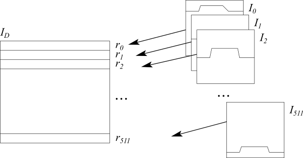
Disparity image \(I_D\)
Image 0, 1, 2, … 511 \(I_0, I_1, I_2 ... I_{511}\)
Row 0, 1, 2 … 511 (profiles of image 0, 1, 2 …511) \(r_0, r_1, r_2 ... r_{511}\)
Note that the disparity image for sheet of light has not exactly the same meaning as the disparity image for stereo matching. For stereo, the disparity describes the difference between the row coordinates of the left and right stereo images, whereas for sheet of light, the disparity is built by the subpixel row values at which the profile was detected.
About the measuring setup🔗
The hardware needed for a sheet-of-light measurement consists of a projector that is able to project a thin luminous line, a camera, a positioning system, and the object to measure. In the following, we assume the projector to be a laser line projector and the positioning system to be linear (e.g., a conveyor belt), as these are very common in laser triangulation applications.
The relation between the projector, the camera, and the linear positioning system must not be changed, whereas the position of the object that is transported by the positioning system changes in relation to the projector-camera unit. Since the profile images are processed column by column, the profiles must be oriented roughly horizontal, i.e., roughly parallel to the rows of the image.
The relation between the laser line projector, the camera, and the object to measure can be described by different measurement setups. Figure 3 shows the three apparent configurations for the three components. In , the camera view is orthogonal to the object and the light plane is tilted. In , the camera view is tilted and the light plane is orthogonal. In , both the camera view and the laser line are tilted.
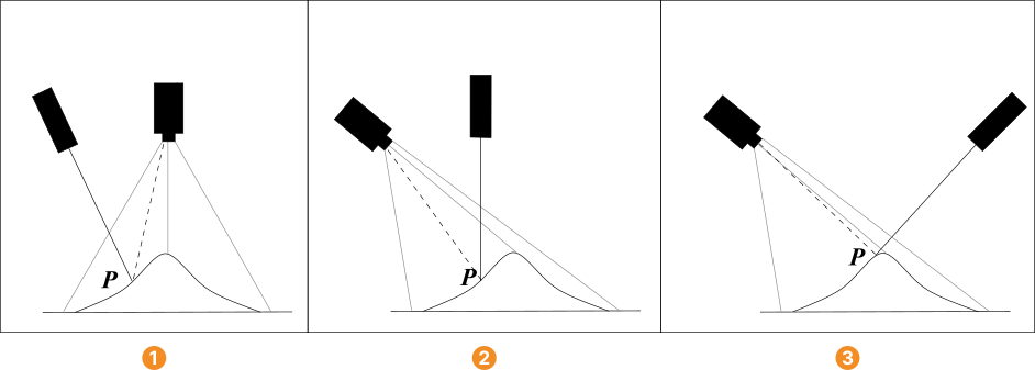
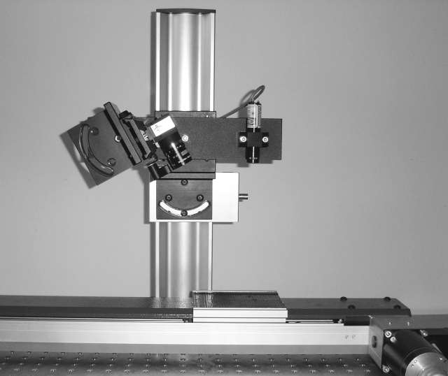
Figure 4 exemplarily shows a measurement setup as it is used for the examples that will be discussed in the following sections.
Which measurement configuration to use depends on the goal of the measurement and the geometry of the object. The configuration in , e.g., is especially suitable if an orthogonal projection of the object in the image is needed for any reason. Then, a cuboid is imaged as a rectangle. For all configurations in which the camera is not placed orthogonal, it would be imaged as a trapezoid because of the perspective deformations (see Figure 5).
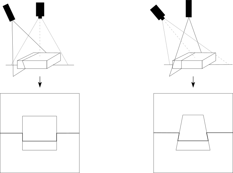
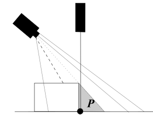
The most important criterion for the selection of the measurement setup is the geometry of the object. The setup should be selected such that the amount of shadowing effects and occlusions is minimized. Occlusions occur if an object point is illuminated by the laser line but is not visible in the image, because other parts of the object lie between the line of sight of the camera and the object point (see Table 1, top). Shadowing effects occur if an object point is visible in the image but is not illuminated by the laser line, because other parts of the object lie between the laser projection and the imaged object point (see Table 1, bottom).
| Problem | Unaffected object point example | Affected object point example |
|---|---|---|
| Occlusion | 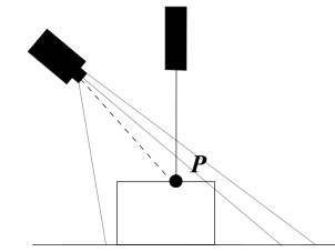 |
 |
| Object point is illuminated and visible in the image | Object point is illuminated but occluded in the image | |
| Shadowing | 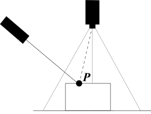 |
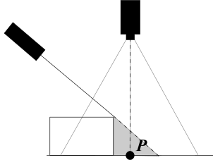 |
| Object point is illuminated and visible in the image | Object point is visible in the image but is not illuminated |
For all three setup configurations, the angle of triangulation, i.e., the angle between the light plane and the optical axis of the camera, should be in a range of 30° to 60° to get a good measurement accuracy. If the angle is smaller, the accuracy decreases. If the angle is larger, the accuracy increases, but more problems because of occlusions and shadowing effects are to be expected. Thus, you have to find a trade-off between the accuracy and the completeness of the measurement.
Additionally, the accuracy decreases if the light plane is out of focus of the camera. That may happen, if the angle of triangulation is too small, i.e., the angle between the light plane and the focus plane is too large, and therefore only a small part near the intersection of both planes is in focus. To overcome this problem, a tilt lens can be used to align the focus plane with the light plane using the Scheimpflug principle and its application in stereo setups.
3D cameras for sheet of light🔗
It is also possible to use specific 3D cameras for which the sheet-of-light measurement is applied inside the camera. These cameras are more expensive than standard 2D cameras, but the sheet-of-light measurement becomes significantly faster because of the reduced CPU load. Using one of these cameras, you simply access the camera with HALCON and basically leave the measurement to the camera.
Generally, we distinguish between cameras with an inbuilt laser, i.e., the camera and the laser are integrated in a single unit, and cameras for which the laser is mounted separately.
If the camera and the laser are integrated in a single unit, the measurement setup is restricted to a fixed angle of triangulation and should be oriented in a defined way. For example, the SICK Ruler camera should be oriented so that the laser is perpendicular to the linear positioning system. Because of the preset measurement setup, the camera and the orientation of the light plane with respect to the world coordinate system are already calibrated. Thus, no further processing with HALCON is needed to obtain calibrated height profiles.
If the camera and the laser are mounted separately, any configuration of the measurement setup is possible , but by default the result of the measurement is uncalibrated. If the result of the measurement is needed in world coordinates, you can either query the uncalibrated data from the camera and subsequently apply a calibration with HALCON, or, before performing the actual measurement, you apply a calibration that is provided specifically for the selected camera. For the SICK Ranger cameras, e.g., the camera-specific calibration needs the software provided with the camera (the SICK Coordinator tool) and a specific calibration object that has to be purchased separately.
Note that in contrast to the proceeding described in the previous sections, the movement of the linear positioning system is mostly assumed to be known, because the measurement of each profile is triggered by a signal coming from an encoder on the linear positioning system. That is, when working with an encoder and if the thus obtained accuracy is sufficient, it is not necessary to calibrate the distance between two profiles.