Stereo system🔗
With a stereo system, i.e., with two or more cameras, you can derive 3D information of the surface of arbitrarily shaped objects. Possible results are distance images, 3D coordinates, or 3D surfaces.
Typical applications of stereo vision comprise, but are not limited to, completeness checks, inspection of ball grid arrays, etc.
Reconstructing surfaces can also serve as a preprocessing step for surface-based 3D matching or 3D primitives fitting. Figure 1 shows a surface reconstructed from four stereo images.
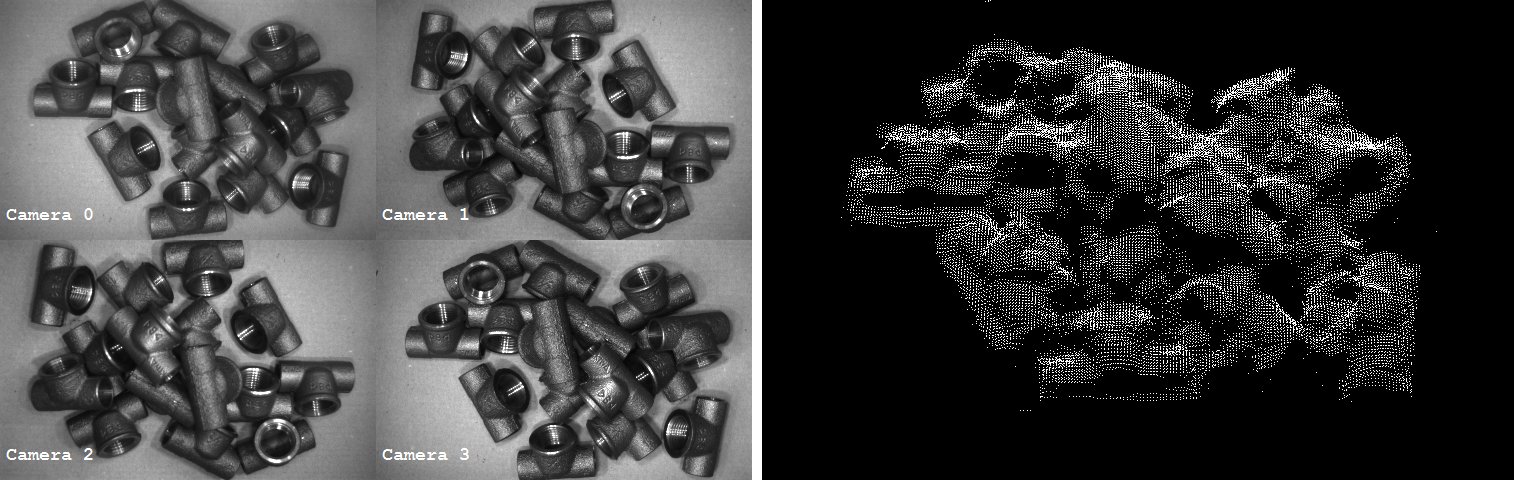
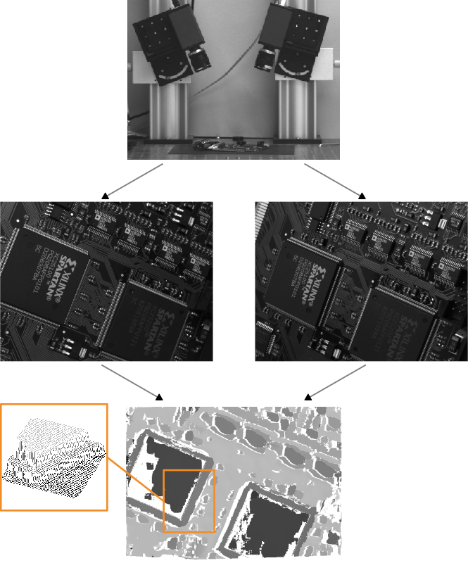
Figure 2 shows an image of a binocular stereo camera system, the resulting stereo image pair, and the height map that has been derived from the reconstructed distance image.
HALCON actually provides two stereo methods:
- Binocular stereo uses exactly two cameras.
- The result is a disparity image, a distance image, or 3D coordinates.
The latter are returned either for selected points or for the complete view. - Multi-view stereo can use more than two cameras.
- Thus, it is able to image the whole 3D object and not just the surface of a specific view.
It returns results in form of 3D surfaces (given as 3D object models) or 3D coordinates of selected points.
The principle of stereo vision🔗
Assume the simplified configuration of two parallel looking 1D cameras with identical internal parameters. Furthermore, the basis, i.e., the straight line connecting the two optical centers of the two cameras, is assumed to coincide with the x-axis of the first camera.
Scheme: Binocular stereo system
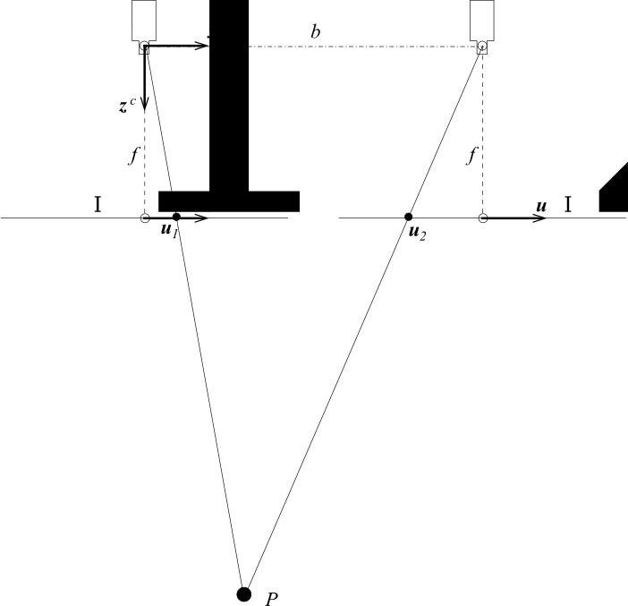
Focal length \(f\)
Baseline length \(b\)
Projection point \(P\)
Image 1 \(I_1\)
Image 2 \(I_2\)
Image plane coordinate system \((u, v)\)
Camera coordinate system \((x^c, y^c, z^c)\)
Then, the image plane coordinates of the projections of the point \(P(x^c,z^c)\) into the two images can be expressed by
where \(f\) is the focal length and \(b\) the length of the basis.
The pair of image points that results from the projection of one object point into the two images is often referred to as conjugate points or homologous points.
The difference between the two image locations of the specialName{conjugate points} is called the specialName{disparity} \(d\):
Given the camera parameters and the image coordinates of two conjugate points, the \(z^c\) coordinate of the corresponding object point \(P\), i.e., its distance from the stereo camera system, can be computed by
Note that the internal camera parameters of both cameras and the relative pose of the second camera in relation to the first camera are necessary to determine the distance of \(P\) from the stereo camera system.
Thus, the tasks to be solved for stereo vision are
- to determine the camera parameters and
- to determine conjugate points.
The first task is achieved by the calibration of the stereo camera system. This calibration is quite similar to the calibration of a single camera. In fact, it even uses the same operators.
The second task is the so-called stereo matching process, which in HALCON is just a call of the operator binocular_disparity (or binocular_distance, respectively) for the correlation-based stereo and a call of the operator binocular_disparity_mg (or binocular_distance_mg, respectively) for multigrid stereo.
Multi-view surface reconstruction extends the basic stereo vision principle to more than one image pair.
There, the matching step is “hidden” in the reconstruction operators, which use the operator binocular_disparity internally to compute disparity images of the individual stereo image pairs.
About stereo camera system setups🔗
The basic stereo camera system consists of two cameras looking at the same object from different positions (see Figure 4). Multi-view stereo systems have additional cameras, but the principle stays the same.
Scheme: Binocular stereo system
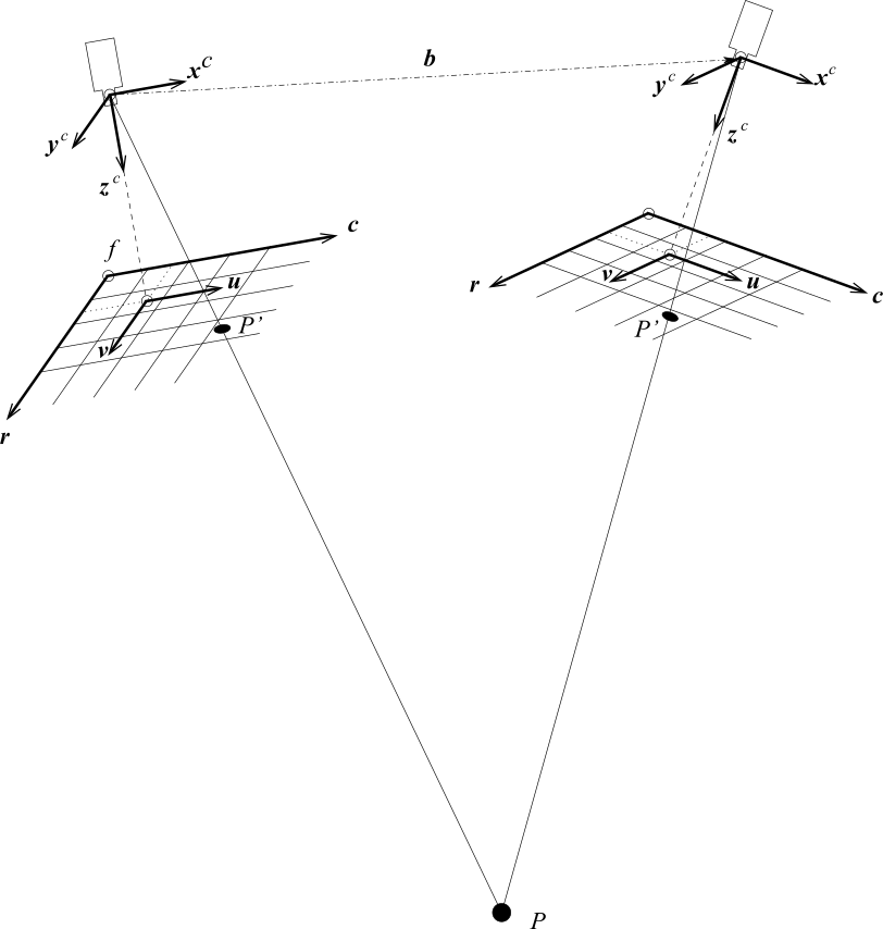
Focal length \(f\)
Baseline length \(b\)
Object point \(P\)
Projection of object point \(P'\)
Image plane coordinate system \((u, v)\)
Image coordinate system \((r ,c)\)
Camera coordinate system \((x^c, y^c, z^c)\)
It is very important to ensure that neither the internal camera parameters (for example, the focal length) nor the relative pose between the cameras changes during the calibration process or between the calibration process and the ensuing application of the calibrated stereo camera system, because the calibration remains valid only as long as the cameras preserve their relative pose. Therefore, it is advisable to mount the cameras on a stable platform.
About the resolution of a stereo camera system🔗
The manner in which the cameras are placed influences the accuracy of the results that is achievable with the stereo camera system.
The distance resolution \(\Delta z\), i.e., the accuracy with which the distance \(z\) of the object surface from the stereo camera system can be determined, can be expressed by
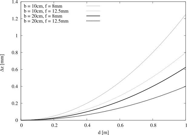
To achieve a high distance resolution, the setup should be chosen such that the length \(b\) of the basis as well as the focal length \(f\) are large, and that the stereo camera system is placed as close as possible to the object. In addition, the distance resolution depends directly on the accuracy \(\Delta d\) with which the disparities can be determined. If the calibration has been performed accurately and the corresponding calibration error is in the order of 0.1 pixels, the disparities typically can be determined with an accuracy of \(1/5\) up to \(1/10\) pixel, which corresponds to approximately 1 μm for a camera with 7.4 μm pixel size. Note that generally the disparities cannot be determined more accurately than the calibration error of the calibration of a stereo camera system.
In Figure 5, the distance resolutions that are achievable in the ideal case are plotted as a function of the distance for four different configurations of focal lengths and base lines, assuming \(\Delta d\) to be 1 μm.
Distance \(d\)
Distance resolution \(∆z\)
Note that if the ratio between \(b\) and \(z\) is very large, problems during the stereo matching process may occur, because the two images of the stereo pair differ too much. The maximum reasonable ratio \(b/z\) depends on the surface characteristics of the object. In general, objects with little height differences can be imaged with a higher ratio \(b/z\), whereas objects with larger height differences should be imaged with a smaller ratio \(b/z\).
If this is difficult to ensure in your application when using two cameras, you should consider using a multi-view stereo system, i.e., more than two cameras.
Optimizing the focus with tilt lenses🔗
For a successful stereo reconstruction, it is necessary that corresponding points of the object appear sharp in both cameras. In some setups, e.g., when using a large magnification or telecentric lenses, this requirement can be difficult to fulfill. This is because the depth of field is small and the angle between the two cameras is relatively large. Therefore, the overlapping area, where the object is in focus from both cameras, may not cover the whole object (see Figure 6).
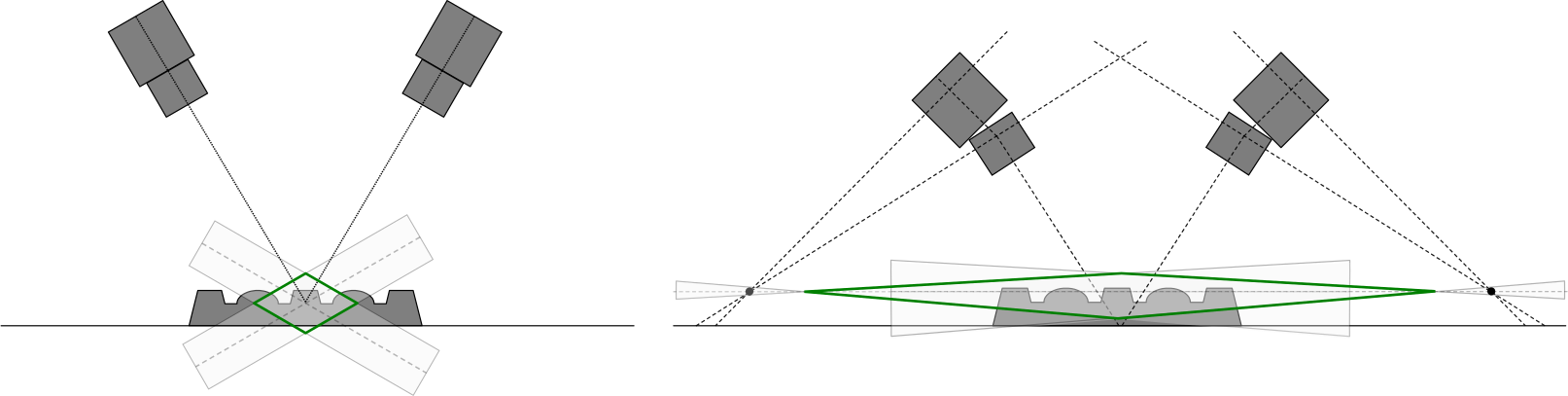
In such cases, tilt lenses can be used to adjust the focus planes of each camera to better fit the object plane.