Binocular stereo vision🔗
With the operators for binocular stereo vision, you can compute disparity and distance images and 3D coordinates using two cameras. In fact, Halcon provides three methods for binocular stereo: correlation-based stereo, multigrid stereo, and multi-scanline stereo.
As an alternative to fully calibrated stereo, Halcon offers the so-called uncalibrated stereo vision. Here, the relation between the cameras is determined from the scene itself, i.e., without needing a special calibration object.
Comparing the different stereo methods🔗
In Halcon, three approaches for stereo matching are available: the traditionally used correlation-based stereo matching, the multigrid stereo matching, and the multi-scanline stereo matching.
The correlation-based stereo matching uses correlation techniques to find corresponding points and thus to determine the disparities or distances for the observed image points.
The disparities or distances are calculated with the operators binocular_disparity or binocular_distance, respectively.
The correlation-based stereo is characterized by the following advantages and disadvantages:
| Advantages | Disadvantages |
|---|---|
| fast | works good only for significantly textured areas; areas without enough texture cannot be reconstructed |
| can be automatically parallelized on multi-core or multi-processor hardware | |
| is invariant against gray-value changes |
The multigrid stereo matching uses a variational approach based on multigrid methods.
This approach returns disparity and distance values also for image parts that contain no texture (as long as these parts are surrounded by significant structures between which an interpolation of values is possible).
The disparities or distances are calculated with the operators binocular_disparity_mg or binocular_distance_mg, respectively.
The multigrid stereo is characterized by the following advantages and disadvantages:
| Advantages | Disadvantages |
|---|---|
| interpolates 3D information for areas without texture based on the surrounding areas | only partially invariant against gray value changes |
| in particular for edges, the accuracy in general is higher than for correlation-based stereo | edges are somewhat blurred |
| the resolution is higher than for correlation-based stereo, i.e., smaller objects can be reconstructed | it cannot be parallelized automatically |
The multi-scanline stereo matching uses a multi-scanline optimization.
Similar to the multigrid approach, it returns disparity and distance values also for image parts that contain only little texture but tries to preserve discontinuities, which are blurred by the multigrid approach.
The disparities or distances are calculated with the operators binocular_disparity_ms or binocular_distance_ms, respectively.
The multi-scanline stereo is characterized by the following advantages and disadvantages:
| Advantages | Disadvantages |
|---|---|
| determines 3D information for areas with little texture | runtime increases significantly with image size and disparity search range |
| preserves discontinuities | high memory consumption |
Accessing calibration results🔗
You access the results of the calibration with the operator get_calib_data.
In addition to the internal camera parameters, we now use the operator also to get the relative pose between the two cameras.
get_calib_data (CalibDataID, 'camera', 0, 'params', CamParamL)
get_calib_data (CalibDataID, 'camera', 1, 'params', CamParamR)
get_calib_data (CalibDataID, 'camera', 1, 'pose', cLPcR)
If you want to perform the calibration in an offline step, you can save the camera setup model with write_camera_setup_model.
write_camera_setup_model (CameraSetupModelID, 'stereo_camera_setup.csm')Acquiring stereo images🔗
The following rules help you to acquire suitable stereo image pairs.
- Do not change the camera setup between the acquisition of the calibration images and the acquisition of the stereo images of the object to be investigated. See here for more information.
- Ensure a proper illumination of the object, e.g., avoid reflections.
- If the object shows no texture, consider to project texture onto it or use multigrid stereo.
- Place the object such that repetitive patterns are not aligned with the rows of the rectified images.
Image Texture🔗
The 3D coordinates of each object point are derived by intersecting the lines of sight of the respective conjugate image points. The conjugate points are determined by an automatic matching process. This matching process has some properties that should be accounted for during the image acquisition.
For each point of the first image, the conjugate point in the second image must be determined. This point matching relies on the availability of texture. The conjugate points cannot be determined correctly in areas without sufficient texture (Figure 1).
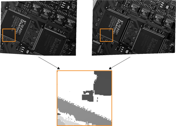
This applies in particular for the correlation-based (binocular) stereo (which is currently the base for multi-view stereo). The multigrid (binocular) stereo, however, can interpolate values in areas without texture. But note that even then, a certain amount of texture must be available to enable the interpolation.
Repetitive Patterns🔗
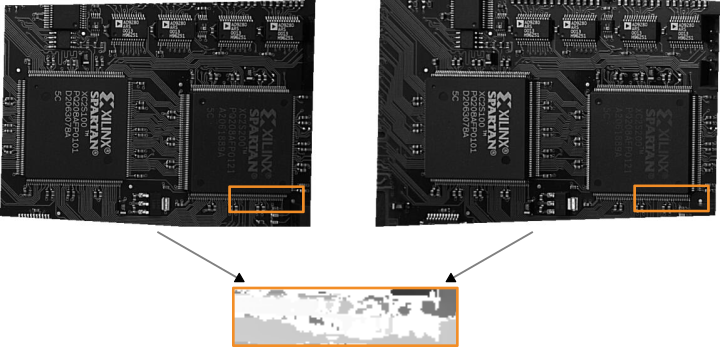
If the images contain repetitive patterns, the matching process may be confused, since in this case many points look alike. In order to make the matching process fast and reliable, the stereo images are rectified such that pairs of conjugate points always have identical row coordinates in the rectified images, i.e., that the search space in the second rectified image is reduced to a line. With this, repetitive patterns can disturb the matching process only if they are parallel to the rows of the rectified images (Figure 2).