Rectifying stereo images🔗
With the internal camera parameters and the relative pose, the stereo images can be rectified, so that conjugate points lie on the same row in both rectified images.
Note that it is assumed that the parameters of the first image of a pair stem from the left image and the parameters of the second image stem from the right image, whereas the notations ‘left’ and ‘right’ refer to the line of sight of the two cameras. If the images are used in the reverse order, they will appear upside down after the rectification.
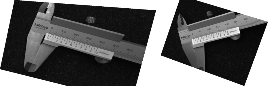
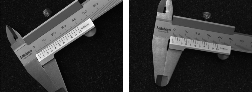
In Figure 1 the original images of a stereo pair are shown, where the two cameras are rotated heavily with respect to each other. The corresponding rectified images are displayed in Figure 2.
The rectification itself is carried out using the operators gen_binocular_rectification_map and map_image.
The operator gen_binocular_rectification_map requires the internal camera parameters of both cameras and the relative pose of the second camera in relation to the first camera.
The parameter SubSampling can be used to change the size and resolution of the rectified images with respect to the original images.
A value of '1' indicates that the rectified images will have the same size as the original images.
Larger values lead to smaller images with a resolution reduced by the given factor, smaller values lead to larger images.
Reducing the image size has the effect that the following stereo matching process runs faster, but also that less details are visible in the result.
In general, it is proposed not to use values below '0.5' or above '2'.
Otherwise, smoothing or aliasing effects occur, which may disturb the matching process.
The rectification process can be described as projecting the original images onto a common rectified image plane.
The method to define this plane can be selected by the parameter Method.
So far, two methods are implemented.
For the method 'geometric' the orientation of the common rectified image plane is defined by the cross product of the base line and the line of intersection of the two original image planes.
The default method, 'viewing_direction', uses the base line as x-axis of the common image plane.
The mean of the viewing directions (z-axes) of the two cameras is used to span the x-z plane of the rectified system.
The resulting rectified z-axis is the orientation of the common image plane and as such located in this plane and orthogonal to the base line.
For perspective cameras, the rectified images can be thought of as being acquired by a virtual stereo camera system, called rectified stereo camera system, as displayed in Figure 3. The optical centers of the rectified cameras are the same as for the real cameras, but the rectified cameras are rotated such that they are looking parallel and that their x-axes are collinear. In addition, both rectified cameras have the same focal length. Therefore, the two image planes coincide. Note that the principal point of the rectified images, which is the origin of the image plane coordinate system, may lie outside the image.
Scheme: Rectified stereo camera system.
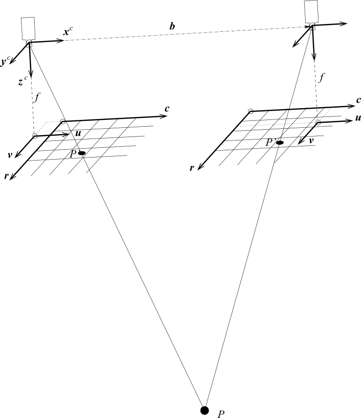
Camera coordinate system \((x^c, y^c, z^c)\)
Image plane coordinate system \((u, v)\)
Image coordinate system \((r ,c)\)
Objective point \(P\)
Projected object point \(P'\)
Focal length \(f\)
Base line \(b\)
The parameter Interpolation specifies whether bilinear interpolation ('bilinear') should be applied between the pixels of the input images or whether the gray value of the nearest pixel ('none') should be used.
Bilinear interpolation yields smoother rectified images, whereas the use of the nearest neighbor is faster.
The operator returns the rectification maps and the camera parameters of the virtual, rectified cameras.
Finally, the operator map_image can be applied to both stereo images using the respective rectification map generated by the operator gen_binocular_rectification_map.
If the calibration was erroneous, the rectification will produce wrong results. This can be checked very easily by comparing the row coordinates of conjugate points selected from the two rectified images. If the row coordinates of conjugate points are different within the two rectified images, they are not correctly rectified. In this case, you should check the calibration process carefully.
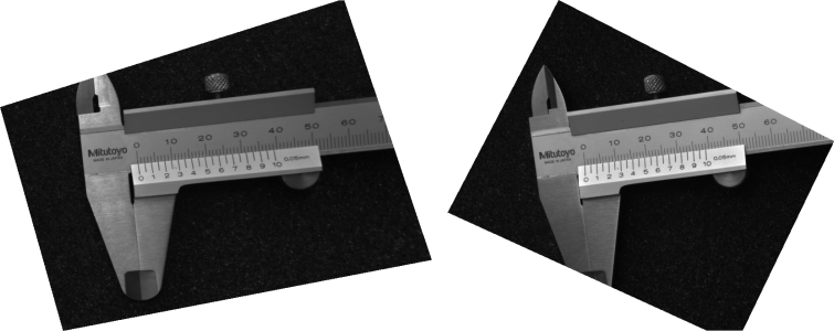
An incorrectly rectified image pair may look like the one displayed in Figure 4.