Calibrating sheet-of-light setups🔗
A sheet-of-light setup can be calibrated in two different ways:
- Calibration using a standard HALCON calibration plate
To calibrate a sheet-of-light setup using a standard HALCON calibration plate, first the camera is calibrated conventionally. Then, the pose of the light plane and the movement of the objects to be measured must be determined based on additional images of the calibration plate.
- Calibration using a special 3D calibration object
For the calibration of a sheet-of-light setup with a special 3D calibration object, first the 3D calibration object must be provided. The calibration itself requires only one (uncalibrated) reconstruction of the 3D calibration object, i.e., its disparity image.
Using HALCON calibration plates🔗
The calibration of the sheet-of-light setup is applied to get the internal and external camera parameters, the orientation of the light plane in the WCS, and the relative movement of the object between two successive measurements. The calibration consists of the following steps:
- Calibrate the camera.
- Determine the orientation of the light plane with respect to the WCS.
- Calibrate the movement of the object relative to the measurement setup.
The camera is calibrated by a standard camera calibration. As result, the camera calibration returns the internal camera parameters and the pose of the WCS relative to the camera coordinate system (external camera parameters).
To determine the light plane and its pose, we need at least three corresponding points (see Figure 1), in particular two points in the plane of the WCS with 'z=0' (P1, P2) and one point that differs significantly in z direction (P3).
Thus, you place the calibration object, e.g., the standard HALCON calibration plate, once or twice so that it lies in the plane of the WCS with 'z=0', and once so that a higher position can be viewed, i.e., the plate is either translated in z direction or it is placed in a tilted position.
For each position of the calibration plate, you take two images, one showing the calibration plate and one showing the laser line.
Note that you have to adapt the lighting in between to get one image with a clearly represented calibration plate and one image that shows a well-defined laser line.
The translated or tilted position of the calibration plate should be selected so that the plane that is built by the points P1, P2, and P3 becomes as large as possible.
The height difference should be at least as big as the height differences expected for the objects to measure.
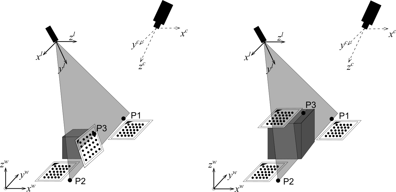
Camera coordinate system \((x^c, y^c, z^c)\)
World coordinate system \((x^w, y^w, z^w)\)
Light plane pose \((x^w, y^w, z^w)\)
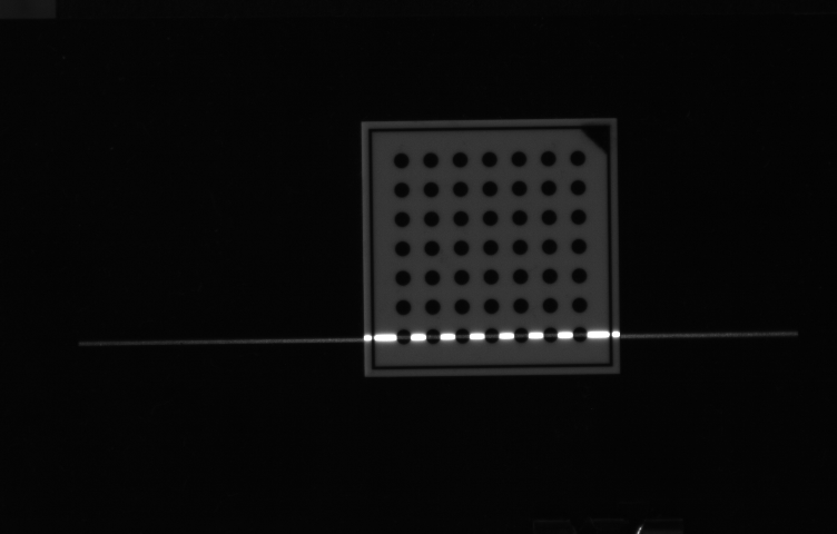
Note that the laser line has to be projected onto the same plane in which the calibration plate is placed. But if possible, it should not be directly projected onto the calibration plate but only near to it. This is because the used standard HALCON calibration plate is made of a ceramic that shows a strong volume scattering. This leads to a broadened profile (see Figure 2), which results in a poor accuracy. If you use a calibration object that consists of a material with different reflection properties, this might be no problem.
Note further that the three corresponding points described above represent the minimum number of points needed to obtain a plane. To enhance the precision of the calibration, redundancy is needed; thus, we recommended to measure more than three corresponding points. Then, the light plane is approximated by fitting a plane into the obtained point cloud.
In the final step, the pose describing the movement of the object must be calibrated using two images containing a calibration plate that was moved by the positioning system by a known number of movement steps.
Summarized, we have to acquire:
- a set of images for the camera calibration,
- at least two images that clearly show the laser line in different planes and which correspond to images that were used for the calibration, and
- at least two images that show the calibration plate in the plane of the linear positioning system. Between the acquisition of the first and the second image, the calibration plate must be moved by the positioning system by a known number of movement steps.
The example program %HALCONEXAMPLES%\hdevelop\Applications\Measuring-3D\calibrate_sheet_of_light_calplate.hdev shows in detail how to calibrate a sheet-of-light measurement setup with a standard HALCON calibration plate.
For the first step, i.e., the camera calibration, initial values for the internal camera parameters and for the thickness of the calibration plate are set.
gen_cam_par_area_scan_polynomial (0.0125, 0.0, 0.0, 0.0, 0.0, 0.0, 0.000006, 0.000006, 376.0, 120.0, 752, 240, StartParameters)
CalTabDescription := 'caltab_30mm.descr'
CalTabThickness := .00063
Then, the calibration images are read. These should fulfill the requirements that are described here. Now, for each image, the calibration plates are searched, the contours and centers of their marks are extracted, and the pose of the calibration plate is estimated. The obtained information is stored in the calibration data model.
NumCalibImages := 20
for Index := 1 to NumCalibImages by 1
    read_image (Image, 'sheet_of_light/connection_rod_calib_' + Index$'.2')
    find_calib_object (Image, CalibDataID, 0, 0, Index, [], [])
endfor
With the obtained data, the actual camera calibration is performed, so that the internal camera parameters (CameraParameters) and the external camera parameters (camera poses) for all calibration images can be obtained.
The internal camera parameters and the camera pose for one of the calibration images are the first two variables that we need for the sheet-of-light measurement that is described in the next section.
calibrate_cameras (CalibDataID, Errors)
get_calib_data (CalibDataID, 'camera', 0, 'params', CameraParameters)
Note that by selecting the camera pose of one of the calibration images you define the origin of the WCS used for the measurement.
For the second step, i.e., the orientation of the light plane in relation to the WCS, the poses of two of the calibration images are needed.
The images show the calibration plates in different heights.
The pose of one image is used to define the WCS and the pose of the other image is used to define a temporary coordinate system (TCS).
For both images, the origins of the poses are shifted with set_origin_pose to consider the thickness of the calibration plate.
Index := 19
get_calib_data (CalibDataID, 'calib_obj_pose', [0,Index], 'pose', CalTabPose)
set_origin_pose (CalTabPose, 0.0, 0.0, CalTabThickness, CameraPose)
Index := 20
get_calib_data (CalibDataID, 'calib_obj_pose', [0,Index], 'pose', CalTabPose)
set_origin_pose (CalTabPose, 0.0, 0.0, CalTabThickness, TmpCameraPose)
For each of the two calibration images a corresponding laser line image was acquired.
There, the laser line is clearly projected onto the same plane that contained the calibration plate in the calibration image.
With the two laser line images and the poses obtained from the two corresponding calibration images the procedure compute_3d_coordinates_of_light_line calculates the 3D coordinates of the points that build the laser lines.
The obtained point cloud consists of the points of the light plane in the plane of the WCS with 'z=0' (see P1 and P2 in Figure 1) and the points of the light plane in the plane of the TCS with 'z=0' (see P3 in Figure 1).
read_image (ProfileImage1, 'sheet_of_light/connection_rod_lightline_019.png')
compute_3d_coordinates_of_light_line (ProfileImage1, MinThreshold, CameraParameters, [], CameraPose, X19, Y19, Z19)
read_image (ProfileImage2, 'sheet_of_light/connection_rod_lightline_020.png')
compute_3d_coordinates_of_light_line (ProfileImage2, MinThreshold, CameraParameters, TmpCameraPose, CameraPose, X20, Y20, Z20)
Now, the procedure fit_3d_plane_xyz fits a plane into the point cloud.
This plane is the light plane, for which the pose is needed as the third variable for the calibrated sheet-of-light measurement.
This pose (LightPlanePose) is calculated from the plane using the procedure get_light_plane_pose.
procedure fit_3d_plane_xyz (X, Y, Z, Ox, Oy, Oz, Nx, Ny, Nz, MeanResidual)
get_light_plane_pose (Ox, Oy, Oz, Nx, Ny, Nz, LightPlanePose)
In the third step, i.e., the calibration of the movement of the object in relation to the measurement setup, the calibration plate is moved in discrete steps by the linear positioning system that will be used also for the following measurement.
To calibrate the movement of the linear positioning system, two images with different movement states are needed.
To enhance the accuracy, we do not use images of two succeeding movement steps but use images with a known number of movement steps between them.
Here, the number of movement steps between both images is 19.
read_image (CaltabImagePos1, 'sheet_of_light/caltab_at_position_1.png')
read_image (CaltabImagePos20, 'sheet_of_light/caltab_at_position_2.png')
StepNumber := 19
Now, for both images the poses of the calibration plates are derived.
find_calib_object (CaltabImagePos1, CalibDataID, 0, 0, NumCalibImages + 1, [], [])
get_calib_data_observ_points (CalibDataID, 0, 0, NumCalibImages + 1, Row1, Column1, Index1, CameraPosePos1)
find_calib_object (CaltabImagePos20, CalibDataID, 0, 0, NumCalibImages + 2, [], [])
get_calib_data_observ_points (CalibDataID, 0, 0, NumCalibImages + 2, Row1, Column1, Index1, CameraPosePos20)
Then, the pose that describes the transformation between these two poses, i.e., the transformation needed for 19 movement steps, is calculated (MovementPoseNSteps).
Note that a rotation is not assumed and therefore all rotational elements are set to 0.
pose_to_hom_mat3d (CameraPosePos1, HomMat3DPos1ToCamera)
pose_to_hom_mat3d (CameraPosePos20, HomMat3DPos20ToCamera)
pose_to_hom_mat3d (CameraPose, HomMat3DWorldToCamera)
hom_mat3d_invert (HomMat3DWorldToCamera, HomMat3DCameraToWorld)
hom_mat3d_compose (HomMat3DCameraToWorld, HomMat3DPos1ToCamera, HomMat3DPos1ToWorld)
hom_mat3d_compose (HomMat3DCameraToWorld, HomMat3DPos20ToCamera, HomMat3DPos20ToWorld)
affine_trans_point_3d (HomMat3DPos1ToWorld, 0, 0, 0, StartX, StartY, StartZ)
affine_trans_point_3d (HomMat3DPos20ToWorld, 0, 0, 0, EndX, EndY, EndZ)
create_pose (EndX - StartX, EndY - StartY, EndZ - StartZ, 0, 0, 0, 'Rp+T', 'gba', 'point', MovementPoseNSteps)
To get the pose for a single movement step (MovementPose), the elements of MovementPoseNSteps that describe a translation are divided by the number of steps.
MovementPose, together with the internal and external camera parameters and the pose of the light plane can now be used to apply a calibrated sheet-of-light measurement.
MovementPose := MovementPoseNSteps / StepNumberFor details about the proceedings inside the stated procedures, we refer to the example.
Using a special 3D calibration object🔗
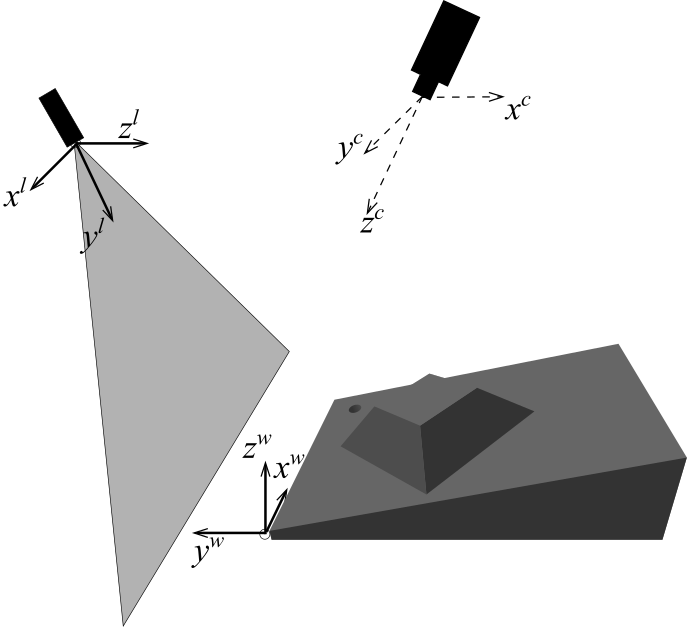
Figure 3 shows a sheet-of-light setup together with a special 3D calibration object.
To calibrate the sheet-of-light setup, one disparity image of the 3D calibration object is acquired with the sheet-of-light setup.
The sheet-of-light setup is then calibrated using this disparity image with the operator calibrate_sheet_of_light.
The calibration of a sheet-of-light setup with a 3D calibration object is simpler but slightly less accurate than the calibration of a sheet-of-light setup with a standard HALCON calibration plate. Nevertheless, first a suitable 3D calibration object must be provided.
In the following, the steps that are necessary for the calibration are described.
The example program %HALCONEXAMPLES%\hdevelop\3D-Reconstruction\Sheet-Of-Light\calibrate_sheet_of_light_3d_calib_object.hdev shows in detail how to calibrate a sheet-of-light setup with a special 3D calibration object.
Supply of a 3D calibration object🔗
A special 3D calibration object must be provided.
This calibration object must correspond to the CAD model created with create_sheet_of_light_calib_object.
The 3D calibration object has an inclined plane on which a truncated pyramid is located.
It has a thinner side, which is hereinafter referred to as front side.
The thicker side is referred to as back side of the calibration object.
Figure 4 shows the 3D calibration object.
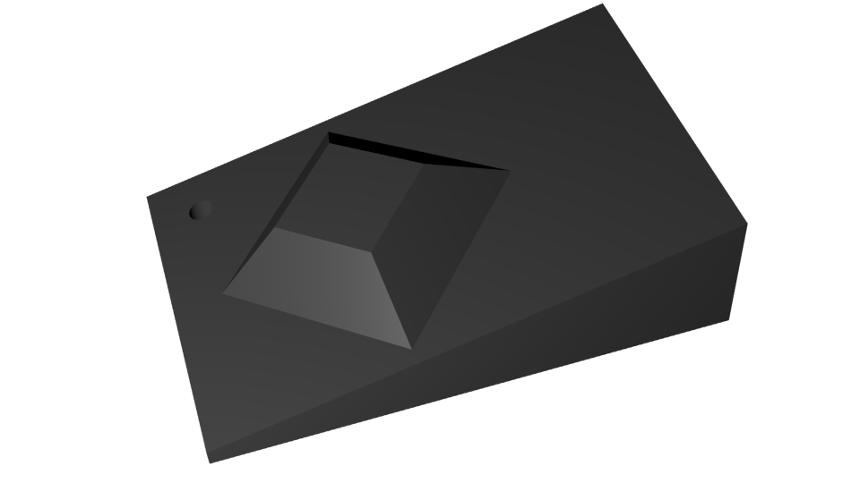
The dimensions of the calibration object should be chosen such that the calibration object covers the complete measuring volume.
Be aware, that only parts on the 3d calibration object above the minimum height of the tilted plane (see the parameter HeightMin of the operator create_sheet_of_light_calib_object) are taken into account.
The CAD model, which is written as a DXF file by create_sheet_of_light_calib_object, also serves as description file of the calibration object.
This CAD model can then be used to manufacture the individual calibration object.
Note that MVTec does not offer such 3D calibration objects.
More information on how to manufacture a calibration object is provided by the description of create_sheet_of_light_calib_object.
Preparing a sheet-of-light model🔗
To prepare a sheet-of-light model for the calibration, the following steps must be performed.
- Create a sheet-of-light model with
create_sheet_of_light_model. - Set the initial parameters of the camera with
set_sheet_of_light_param. So far, only pinhole cameras with the division model are supported. - Set the description file of the calibration object (created with
create_sheet_of_light_calib_object) withset_sheet_of_light_param.
create_sheet_of_light_model (Domain, [], [], SheetOfLightModelID)
set_sheet_of_light_param (SheetOfLightModelID, 'camera_parameter', CameraParam)
set_sheet_of_light_param (SheetOfLightModelID, 'calibration_object', 'calib_object.dxf'
Uncalibrated reconstruction of the 3D calibration object🔗
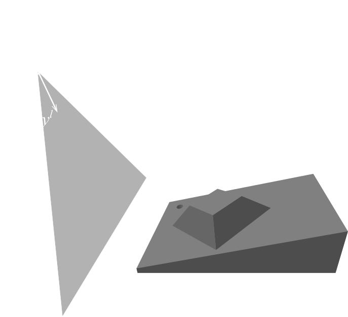
The 3D calibration object must be reconstructed with the (uncalibrated) sheet-of-light model prepared above, i.e., a disparity image of the 3D calibration object must be created (see Figure 5).
for Index := 1 to 1000 by 1
    measure_profile_sheet_of_light (ProfileImage, SheetOfLightModelID, [])
endfor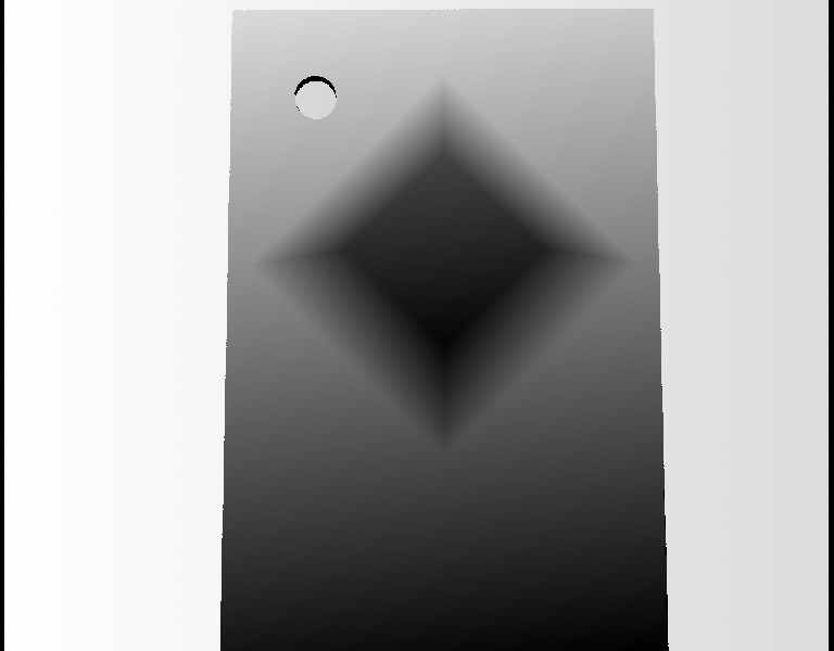
For this, the calibration object must be oriented such that either its front side or its back side intersect the light plane first (i.e., the movement vector should be parallel to the Y axis of the calibration object, see Figure 3 or create_sheet_of_light_calib_object).
As far as possible, the domain of the disparity image of the calibration object should be restricted to the calibration object.
Besides, the domain of the disparity image should have no holes on the truncated pyramid.
All four sides of the truncated pyramid must be clearly visible.
If the disparity image is already provided by the camera, it can be set with set_sheet_of_light_param directly.
set_profile_sheet_of_light (CalibObjectDisparity, SheetOfLightModelID, [])Calibration of the sheet-of-light setup🔗
The calibration is then performed with calibrate_sheet_of_light.
calibrate_sheet_of_light (SheetOfLightModelID, Error)The returned error is the RMS of the distance of the reconstructed points to the calibration object in meters.
For sheet-of-light models calibrated with calibrate_sheet_of_light, you can obtain the calibrated camera parameters, camera pose, light plane pose, and movement pose using get_sheet_of_light_param.