Transforming image to world coordinates and vice versa🔗
Based on the calibration data, world coordinates can now be obtained from images. On the one hand, it is possible to process the images as usual and then to transform the extraction results into the world coordinate system. In many cases, this will be the most efficient way of obtaining world coordinates. On the other hand, some applications may require that the segmentation itself must be carried out in images that are already transformed into the world coordinate system.
In general, the segmentation process reduces the amount of data that needs to be processed. Therefore, rectifying the segmentation results is faster than rectifying the underlying image. What is more, it is often better to perform the segmentation process directly on the original images because smoothing or aliasing effects may occur in the rectified image, which could disturb the segmentation and may lead to inaccurate results. These arguments suggest to rectify the segmentation results instead of the images.
In the following, first some general remarks on the underlying principle of the transformation of image coordinates into world coordinates are given. Then, it is described how to transform points, contours, and regions into the world coordinate system. Finally, we show that it is possible to transform world coordinates into image coordinates as well, for example, in order to visualize information given in the world coordinate system.
Given the image coordinates of one point, the goal is to determine the world coordinates of the corresponding point in the measurement plane. For this, the line of sight, that is, a straight line from the optical center of the camera through the given point in the image plane, must be intersected with the measurement plane.
Scheme: Intersecting the line of sight with the measurement plane

Camera coordinate system \((x^c, y^c, z^c)\)
World coordinate system \((x^w, y^w, z^w)\)
Image plane coordinate system \((u, v)\)
Image coordinate system \((r, c)\)
Measurement plane \(z^w = 0\)
The calibration data is necessary to transform the image coordinates into camera coordinates and finally into world coordinates.
All these calculations are performed by the operators of the family ..._to_world_plane.
Again, please remember that in HALCON the measurement plane is defined as the plane \(z=0\) with respect to the world coordinate system.
This means that all points returned by the operators of the family ..._to_world_plane have a \(z\)-coordinate equal to zero, that is, they lie in the plane \(z=0\) of the world coordinate system.
Image points to world coordinates🔗
The world coordinates of an image point \((r,c)\) can be determined using the operator image_points_to_world_plane.
In the following code example, the row and column coordinates of pitch lines are transformed into world coordinates.
As input, the operator requires the internal and external camera parameters as well as the row and column coordinates of the point(s) to be transformed.
Additionally, the unit in which the resulting world coordinates are to be given is specified by the parameter Scale.
This parameter is the ratio between the unit in which the resulting world coordinates are to be given and the unit in which the world coordinates of the calibration target are given.
In many cases the coordinates of the calibration target are given in meters.
In this case, it is possible to set the unit of the resulting coordinates directly by setting the parameter Scale to 'm' (corresponding to the value 1.0, which could be set alternatively for the parameter Scale), 'cm' (0.01), 'mm' (0.001), or 'microns' (1e-6).
Then, if the parameter Scale is set to, for example, 'm', the resulting coordinates are given in meters.
If, for example, the coordinates of the calibration target are given in micrometers (μm) and the resulting coordinates have to be given in millimeters, the parameter Scale must be set to:
Contours to world coordinates🔗
If you want to convert an XLD object containing pixel coordinates into world coordinates, the operator contour_to_world_plane_xld can be used.
Its parameters are similar to those of the operator image_points_to_world_plane.
lines_gauss (ImageReduced, Lines, 1, 3, 8, 'dark', 'true', 'bar-shaped', 'true')
contour_to_world_plane_xld (Lines, ContoursTrans, CamParam, PoseAdapted, 1)
Regions to world coordinates🔗
In HALCON, regions cannot be transformed directly into the world coordinate system.
Instead, you must first convert them into XLD contours using the operator gen_contour_region_xld, then apply the transformation to these XLD contours as described in the previous section.
If the regions have holes and if these holes would influence your further calculations, set the parameter Mode of the operator gen_contour_region_xld to 'border_holes'.
Then, in addition to the outer border of the input region the operator gen_contour_region_xld returns the contours of all holes.
World coordinates to image coordinates🔗
In this section, the transformation between image coordinates and world coordinates is performed in the opposite direction, that is, from world coordinates to image coordinates. This is useful if you want to visualize information given in world coordinates or it may be helpful for the definition of meaningful regions of interest (ROI).
First, the world coordinates must be transformed into the camera coordinate system.
For this, the homogeneous transformation matrix \(\mvHomMatrixVar{CCS}{WCS}\) is needed, which can easily be derived from the pose of the measurement plane with respect to the camera by the operator pose_to_hom_mat3d.
The transformation itself can be carried out using the operator affine_trans_point_3d.
Then, the 3D coordinates, now given in the camera coordinate system, can be projected into the image plane with the operator project_3d_point.
An example program is given in the following:
There, the world coordinates of four points defining a rectangle in the WCS are defined.
Then, the transformation matrix \(\mvHomMatrixVar{CCS}{WCS}\) is derived from the respective pose.
With this transformation matrix, the world points are transformed into the camera coordinate system.
affine_trans_point_3d (CCS_HomMat_WCS, ROI_X_WCS, ROI_Y_WCS, ROI_Z_WCS, CCS_RectangleX, CCS_RectangleY, CCS_RectangleZ)
Finally, the points are projected into the image coordinate system.
project_3d_point (CCS_RectangleX, CCS_RectangleY, CCS_RectangleZ, CamParam, RectangleRow, RectangleCol)
Compensating lens distortions only🔗
All operators discussed above automatically compensate for lens distortions. In some cases, you might want to compensate for lens distortions only without transforming results or images into world coordinates.
Note that in the following, only the compensation for radial distortions using the division model is described. The compensation for radial and decentering distortions using the polynomial model is done analogously by replacing \(\kappa=0\) with \(K_{1} = K_{2} = K_{3} = P_{1} = P_{2} = 0\).
The procedure is to specify the original internal camera parameters and those of a virtual camera that does not produce lens distortions, that is, with \(\kappa=0\).
The easiest way to obtain the internal camera parameters of the virtual camera would be to simply set \(\kappa\) to zero. This can be done directly by changing the respective value of the internal camera parameters.
CamParVirtualFixed := CamParOriginal
set_cam_par_data (CamParVirtualFixed, 'kappa', 0, CamParVirtualFixed)
Alternatively, the operator change_radial_distortion_cam_par can be used with the parameter Mode set to 'fixed' and the parameter DistortionCoeffs set to 0.
Then, for the rectification of the segmentation results, the HALCON operator change_radial_distortion_contours_xld can be used, which requires as input parameters the original and the virtual internal camera parameters.
If you want to change the lens distortion of image coordinates (Row, Col), you can alternatively use change_radial_distortion_points.
change_radial_distortion_contours_xld (Edges, EdgesRectifiedFixed, CamParOriginal, CamParVirtualFixed)
The rectification of the segmentation results changes the visible part of the scene (see images below).
To obtain virtual camera parameters such that the whole image content lies within the visible part of the scene, the parameter Mode of the operator change_radial_distortion_cam_par must be set to 'fullsize'.
Again, to eliminate the lens distortions, the parameter DistortionCoeffs must be set to 0, or all coefficients of the polynomial model must be set to zero, respectively.
If the lens distortions are eliminated in the image itself, the mode 'fullsize' may lead to undefined pixels in the rectified image.
The mode 'adaptive' slightly reduces the visible part of the scene to prevent such undefined pixels.
The mode 'preserve_resolution' works similar to the mode 'fullsize' but prevents undefined pixels by additionally increasing the size of the modified image so that the image resolution does not decrease in any part of the image.
change_radial_distortion_cam_par ('preserve_resolution', CamParOriginal, 0, CamParVirtualPreservedResolution)
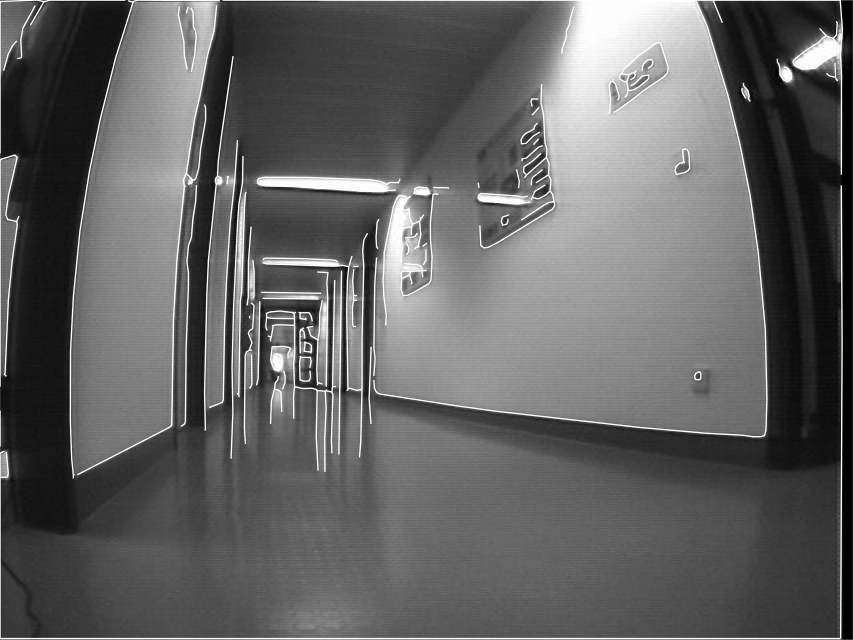
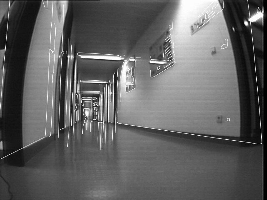
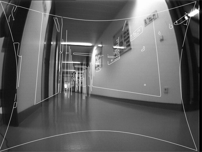
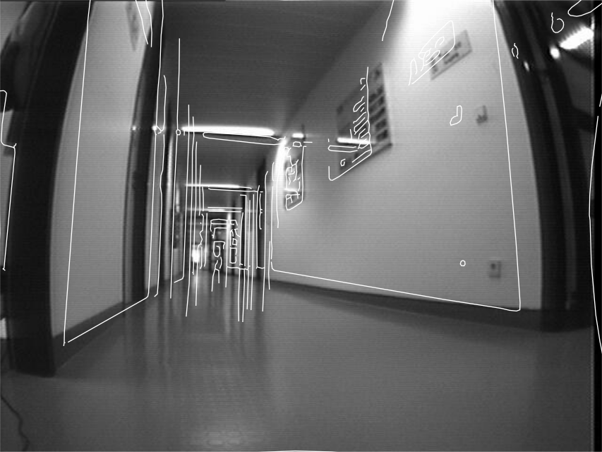
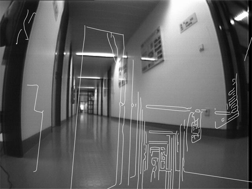
Note that this compensation for lens distortions is not possible for pinhole line scan images because of the acquisition geometry of pinhole line scan cameras. To eliminate radial distortions from segmentation results of pinhole line scan images, the segmentation results must be transformed into the WCS.
For telecentric line scan cameras, the lens distortion compensation works in an identical manner as for area scan cameras.
In addition, for telecentric line scan cameras, the motion vector also influences the perceived distortion.
For example, a nonzero \(V_x\) component leads to skewed pixels.
Furthermore, if \(V_y \ne S_x / m\), where \(m\) is the magnification of the lens, the pixels appear to be non-square.
Therefore, for telecentric line scan cameras, up to three more components can be passed in addition to \(\kappa\) in DistortionCoeffs.
These specify the new \(V_x\), \(V_y\), and \(V_z\) components of the motion vector.
In particular, setting \(V_x\) to 0 and \(V_y\) to \(S_x / m\) results in square pixels in the output image if Mode is set to 'fixed'.