Rectifying images🔗
For applications like blob analysis or OCR, it may be necessary to have undistorted images. Imagine that an OCR has been trained based on undistorted image data. Then, it will not be able to recognize characters in heavily distorted images. In such a case, the image data must be rectified, i.e., the lens and perspective distortions must be eliminated before the OCR can be applied.
Transforming images into the world coordinate system🔗
The operator image_to_world_plane rectifies an image by transforming it into the measurement plane, that is, the plane \(z=0\) of the world coordinate system (WCS).
The rectified image shows no lens and no perspective distortions.
It corresponds to an image captured by a camera that produces no lens distortions and that looks perpendicularly to the measurement plane.
image_to_world_plane (Image, ImageMapped, CamParam, PoseForCenteredImage, WidthMappedImage, HeightMappedImage, ScaleForCenteredImage, 'bilinear')If more than one image must be rectified, a projection map can be determined with the operator gen_image_to_world_plane_map, which is used analogously to the operator image_to_world_plane, followed by the actual transformation of the images, which is carried out by the operator map_image.
gen_image_to_world_plane_map (Map, CamParam, PoseForCenteredImage, WidthOriginalImage, HeightOriginalImage, WidthMappedImage, HeightMappedImage, ScaleForCenteredImage, 'bilinear')
map_image (Image, Map, ImageMapped)
The size of the rectified image can be chosen with the parameters Width and Height for the operator image_to_world_plane and with the parameters WidthMapped and HeightMapped for the operator gen_image_to_world_plane_map.
The size of the rectified image must be given in pixels.
The pixel size of the rectified image is specified by the parameter Scale.
This parameter is the ratio between the pixel size of the rectified image and the unit in which the world coordinates of the calibration target are given.
where \(p\) is the pixel size of the rectified image and \(u\) is the unit of world coordinates of the calibration target.
In many cases the coordinates of the calibration targets are given in meters.
In this case, it is possible to set the pixel size directly by setting the parameter Scale to 'm' (1.0), 'cm' (0.01), 'mm' (0.001), or 'microns' (1e-6).
Then, if the parameter Scale is set to, for example, 'microns', one pixel of the rectified image has a size that corresponds to an area of 1 μm × 1 μm.
The parameter Scale should be chosen such that in the center of the area of interest the pixel size of the input image and of the rectified image is similar.
Large scale differences would lead to aliasing or smoothing effects.
See below for examples of how the scale can be determined.
The parameter Interpolation specifies whether bilinear interpolation ('bilinear') should be applied between the pixels in the input image or whether the gray value of the nearest neighboring pixel ('none') should be used.
The rectified image ImageWorld is positioned such that its upper left corner is located exactly at the origin of the WCS and that its column axis is parallel to the x-axis of the WCS.
Since the WCS is defined by the external camera parameters CamPose the position of the rectified image ImageWorld can be translated by applying the operator set_origin_pose to the external camera parameters.
Arbitrary transformations can be applied to the external camera parameters based on homogeneous transformation matrices.
See below for examples of how the external camera parameters can be set.
In Figure 1, the WCS has been defined such that the upper left corner of the rectified image corresponds to the upper left corner of the input image. To illustrate this, in Figure 1, the full domain of the rectified image, transformed into the virtual image plane of the input image, is displayed. As can be seen, the upper left corner of the input image and of the projection of the rectified image are identical.
Note that it is also possible to define the WCS such that the rectified image does not lie or lies only partly within the imaged area. The domain of the rectified image is set such that it contains only those pixels that lie within the imaged area, that is, for which gray value information is available. In Figure 2, the WCS has been defined such that the upper part of the rectified image lies outside the imaged area. To illustrate this, the part of the rectified image for which no gray value information is available is displayed dark gray. Also in Figure 2, the full domain of the rectified image, transformed into the virtual image plane of the input image, is displayed. It can be seen that for the upper part of the rectified image no image information is available.
Scheme: Projection of the image into measurement plane
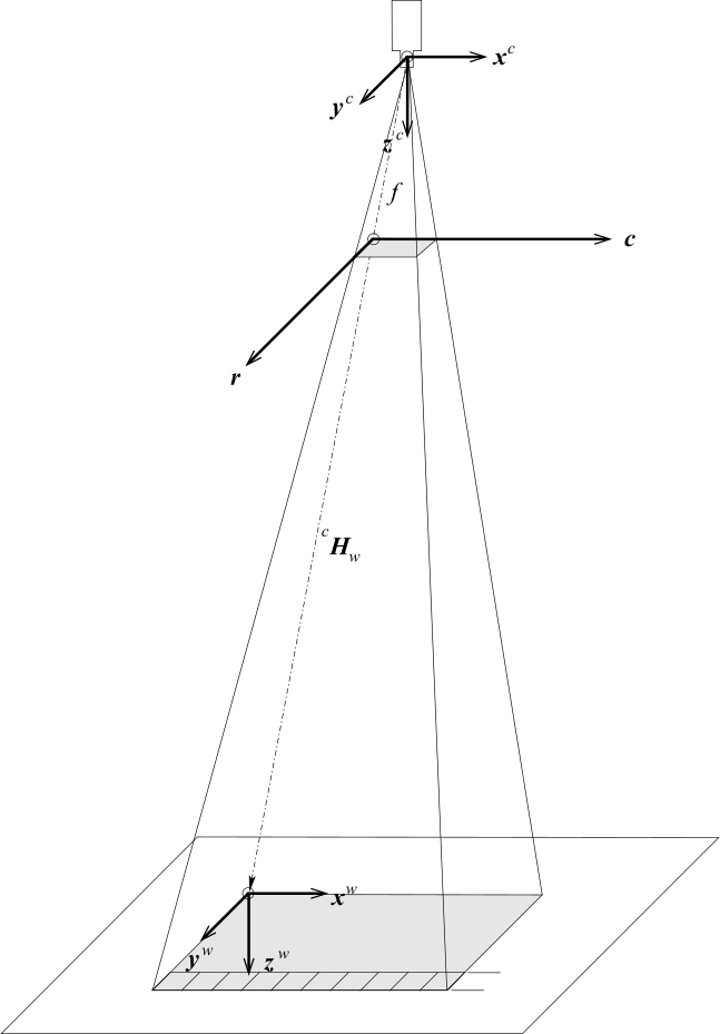
Camera coordinate system \((x^c, y^c, z^c)\)
World coordinate system \((x^w, y^w, z^w)\)
Image coordinate system \((r ,c)\)
Measurement plane \(z^w = 0\)
Pixel height/width = Scale \(\cdot\) unit
Scheme: Projection of the image into measurement plane with part outside image area
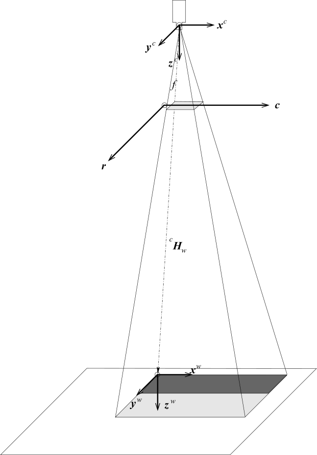
Camera coordinate system \((x^c, y^c, z^c)\)
World coordinate system \((x^w, y^w, z^w)\)
Image coordinate system \((r ,c)\)
Measurement plane \(z^w = 0\)
If several images must be rectified using the same camera parameters the operator gen_image_to_world_plane_map in combination with map_image is much more efficient than the operator image_to_world_plane because the transformation must be determined only once.
In this case, a projection map that describes the transformation between the image plane and the world plane is generated first by the operator gen_image_to_world_plane_map.
Then, this map is used by the operator map_image to transform the image very efficiently.
The example from %HALCONEXAMPLES%\solution_guide\3d_vision\transform_image_into_wcs.hdev shows how to perform the transformation of images into the world coordinate system using the operators gen_image_to_world_plane_map together with map_image as well as the operator image_to_world_plane.
Compensate for lens distortions only🔗
The principle of the compensation for lens distortions is also described here.
If only one image must be rectified the operator change_radial_distortion_image can be used.
It is used analogously to the operator change_radial_distortion_contours_xld, with the only exception that a region of interest (ROI) can be defined with the parameter Region.
change_radial_distortion_image (GrayImage, ROI, ImageRectifiedAdaptive, CamParOriginal, CamParVirtualAdaptive)
Again, the internal parameters of the virtual camera that does not show lens distortions can be determined by setting \(\kappa\) to zero for the division model or \(K_1\), \(K_2\), \(K_3\), \(P_1\), and \(P_2\) to zero for the polynomial model.
Alternatively, the internal parameters of the virtual camera can be obtained by using the operator change_radial_distortion_cam_par with the parameter Mode.
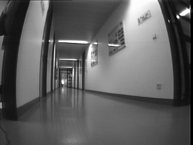
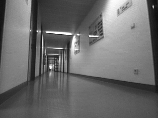
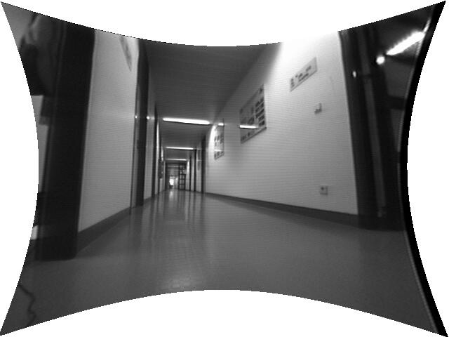
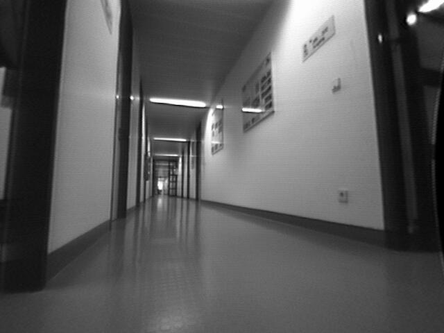
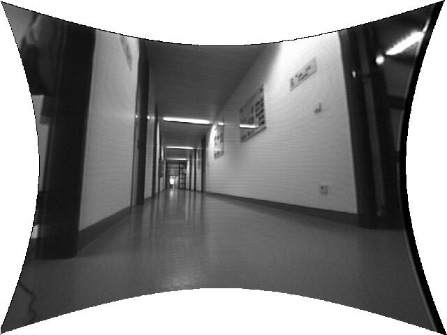
If more than one image must be rectified, a projection map can be determined with the operator gen_radial_distortion_map, which is used analogously to the operator change_radial_distortion_image, followed by the actual transformation of the images, which is carried out by the operator map_image.
If a ROI is to be specified, it must be rectified separately.
gen_radial_distortion_map (MapFixed, CamParOriginal, CamParVirtualFixed, 'bilinear')
map_image (GrayImage, MapFixed, ImageRectifiedFixed)
Note that this compensation for lens distortions is not possible for pinhole line scan images because of the acquisition geometry of pinhole line scan cameras. To eliminate radial distortions from pinhole line scan images, the images must be transformed into the WCS.
For telecentric line scan cameras, the compensation of lens distortions works in and identical manner as for area scan cameras.