Optimization🔗
Speed🔗
To speed up the matching process, there are two major approaches:
Use a straightforward parameter set, for example, choose the fast option when determining the normal computation of the model, or reduce the number of points by an appropriate pre-processing step on the point cloud.
Features regarding 3D model and scene, which can affect the speed are listed in the following sections.
Model🔗
-
Complexity of the model:
The more surfaces the model contains, the slower the training and matching process. This is especially the case if'train_3d_edges'is enabled. In such cases, the model should be simplified as much as possible, for instance, withsimplify_object_model_3d. -
Inner structure of the model:
A slowdown can be due to the fact that the model contains non-visible surfaces inside. Such triangles need to be removed.
Scene🔗
-
Sampling distance:
The larger the sampling distance, the smaller the amount of data points and thus the faster the object localization process. However, the sampling distance should be set such that at least 150 points are distributed on the object. Moreover, in case smaller or thinner shapes are to be considered, the sampling distance should be set such that enough points are distributed over the smaller or thinner shape as well. For instance, if a long and thin object should be localized, the sampling distance should be set such that it is at least one fourth of the smaller extension of the object. -
Shape of the model:
In case of flat objects, the optimization process will take longer. In such cases, it is recommended to segment the scene and to apply the surface matching in a loop of the segmented components. -
Disable 3D edge alignment:
When applying surface-based matching with surface information, 3D and 2D edge information, 3D edge alignment can be disabled, which can speed up the matching, especially if handling noisy point clouds. This can be done by setting'use_3d_edges'to be'false'. -
Use XYZ-mappings:
XYZ-mapping-based processing is much faster than point cloud processing due to the already available information structure or order. Note that you can also enhance the preprocessing of your 3D data, by applying it to the XYZ-images. -
Duplicate points:
Duplicate points lead to slower processing. The presence of duplicate points can be checked and removed. -
Number of points:
If there are a lot of scene points that lie on the object instance and/or the point cloud is very dense, it is recommended to increase the value set for the generic parameter'pose_ref_sub_sampling'. -
Remove outliers:
Useselect_points_object_model_3dwith the parameter'num_neighbors_fast'to remove outliers. -
Remove noise:
Noise can be removed with one of the following approaches:median_imageon the Z-mapping. Note that if smoothing is applied on the Z-image , artifacts appear in the XY-plane at Z=0. Therefore, a threshold should be carried out afterwards with a value that excludes all Z=0 values.- Apply a standard blob analysis on the Z-mapping. Remove smaller blobs from the image domain and reduce the scene to the new domain by applying
reduce_object_model_3d_by_vieworxyz_to_object_model_3d.
-
Remove background:
Generally, the fewer the points to be processed, the faster the matching. In most cases, an adequate preprocessing can speed up the application significantly. Such a preprocessing can be applied on the XYZ-mappings or on the point cloud.
Robustness🔗
Higher robustness can especially be achieved by improving the significance of the computed scores. There are three major parameters that can be used to improve the matching concerning its robustness.
-
Key point fraction:
Increasing the number of key points increases the number of approximate matching poses, and therefore, more poses are available to be analyzed in the following two refinement steps. Note that this increases the processing time as well. -
Sampling distance:
If the model contains a finer structure or a high density of geometrical information, reducing the sampling distance leads to more robust results. Note that the distance should be defined such that the characteristic features of the model are displayed fine enough (see Figure 1 for an example case with a long and thin object).
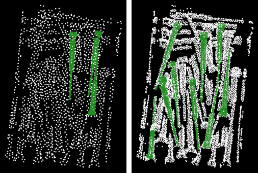
RelSamplingDistance= 0.03 (left) and RelSamplingDistance= 0.15 (right). - Point thresholding:
In case 3D edges with nonlinear trajectories are available, that is, edges of a box are rather round, matching results and scores can be improved by increasing the values of'pose_ref_dist_threshold_edges_rel'or'pose_ref_dist_threshold_edges_abs'.
Robustness and scores can further be affected by the parameters listed below.
-
Duplicate points:
Duplicate points can also lead to less robust results. Therefore, it is highly recommended to remove them before any further processing. -
Normal directions:
If model normals and scene normals do not point approximately in the same direction, matching results are not robust or matching will not work at all. -
Shape:
Shapes with reduced 3D information lead to lower robustness. Therefore, in such cases it is highly recommended to preprocess the data in a suitable way and use edge-supported surface-based matching -
View-based score:
The view-based score only considers those model points, that are potentially visible from the determined viewpoint. Therefore the robustness of the matching results increases as this score is more expressive. -
Maximum overlap:
Due to efficiency reasons, the generic parameters'max_overlap_dist_rel'/'max_overlap_dist_abs'are based on the distance of the centers of the axis oriented bounding boxes of neighboring objects in the scene. Therefore, in case of long and thin objects, the generic parameters should be set to a much lower value (at about the smallest extension of the object, see Figure 2). However, this also leads to overlapping matching results, which need to be filtered out in a post-processing step.
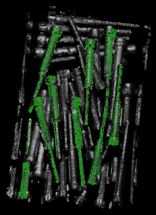
'max_overlap_dist_abs' is set to 4.5 mm and the sampling distance is set to 0.6 mm. - Self-similarities:
The pose of objects that are almost symmetric are sometimes hard to distinguish forfind_surface_model. Enable the generic parameter'train_self_similar_poses'when creating the surface model to avoid this.
Accuracy🔗
The internal refinement algorithm has a maximum achievable accuracy.
This accuracy limitation is due to numerical constraints linked to the internal processing of data and variables. The maximum error is at around 1e-3 (or 0.1%), but can be practiced at around 1e-7 times the size (diameter) of the model, or 0.00001%. Note that this is the maximum accuracy that can be achieved if all the conditions are perfect.
The model size affects the (absolute) accuracy because coordinates are stored as float values. This is one reason why the accuracy is relative to the model size. For example, if the scale of the model and the scenes is changed (for example, by multiplying all model and scene coordinates with the factor 1000000, the absolute accuracy would also change by the factor 1000000). In contrast, the accuracy in relation to the model diameter would remain the same.
The following features can affect the accuracy:
-
Model shape:
Some models have shapes which allow certain degrees of freedom for the pose. For example, planar objects can translate and rotate on a scene plane without changing the score too much. Note that sometimes this can be avoided by using edge-supported surface-based matching. This applies to all self-similar or symmetric shapes: Cylinders, spheres, planar objects etc. -
Visible part of the object instance:
Even if the shape of the object is suitable, for example, in the case of a box, it can happen that only a small part of the object is visible, for instance, a small part of one side of the box. In this case, the translation and rotation inside that one box side cannot be properly determined. Ideally, several orthogonal sides of the object instance should be visible, so that the translation (and rotation) are fixed in all directions. -
Number of scene points that lie on the model:
If only few scene points represent an instance of the object, no high accuracy can be achieved. -
Point noise from the sensor:
More accurate input points will also lead to a more accurate pose. Note for example that time-of-flight sensors can cause noise deviations up to 1 cm, whereas sheet-of-light setups might lead to 0.1 mm noise; so, coarsely, there are 2 orders of magnitude of difference. -
Object position in scene coordinates:
The further away an instance is from the origin of the scene, the smaller the possible accuracy is. For example, if an object is 1000 times its diameter away from the origin of the scene, the accuracy drops by a factor of up to 1000. This is because the coordinates are stored as float values, and they will lose some of their significant bits. It is always advisable to keep the scene origin at about 10–100 times the diameter of the model away from its instances at most. -
Refinement sampling distance:
The sampling distance of the model in the refinement step also affects the final accuracy. It can be set using the generic parameter'pose_ref_rel_sampling_distance'of the operatorcreate_surface_model. With a smaller value, the accuracy can improve, especially if the model contains parts with high curvature or high frequency. It is possible to inspect the impact on the model used in the refinement step using the operatorget_surface_model_paramwith the parameter'sampled_pose_refinement'. The sampled point cloud should represent the object, including its fine structures. Parts that are not represented by this point cloud are not used during the refinement.
Background removal🔗
Removing the background from your scene before the matching can be useful in many cases. There are various different methods available to remove background or to reduce the scene to the objects to be located. In the following, different approaches are described that show how to remove the background plane or bins from the 3D scene.
You can also step through these examples, which demonstrate the workflows explained in the following sections:
remove_bin_for_3d_object_localization.hdevremove_background_for_3d_object_localization.hdev
Background plane🔗
Orthogonal camera setup🔗
In case height is not changing and the 3D sensor or acquisition setup is mostly orthogonal to the background plane, the background plane can be removed by applying a simple threshold on the Z-mapping (if available) or on the 3D point cloud.
A threshold on the Z-mapping can be applied using the following operators
threshold (ImageZ, Regions, MinThres, MaxThres)
reduce_object_model_3d_by_view (Regions, Scene, [], [], SceneReduced)
To remove the background plane without using a Z-mapping, the following operator calls can be executed:
select_points_object_model_3d (Scene, 'point_coord_z', MinThres, MaxThres, ObjectModel3DReduced)Tilted camera setup🔗
In case the 3D sensor is tilted with respect to the background plane, in a first step, it can be approximated by a plane estimation. In a second step the point cloud will be leveled such that the above-mentioned method can be used to remove the background plane.
- Acquire a reference scene. Then, define a ROI on gray values that describe the background plane. The approximate background plane can be estimated by the following lines of codes:
intersection (ROI, ImageZ, RegionIntersection)
fit_surface_first_order (RegionIntersection, ImageZ, 'regression', 5, 2, Alpha, Beta, Gamma)
area_center (RegionIntersection, Area, Row, Column)
get_image_size (ImageZ, Width, Height)
gen_image_surface_first_order (BackgroundPlane, 'real', Alpha, Beta, Gamma, Row, Column, Width, Height)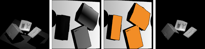
- Remove the background plane from the online acquired scene by subtracting the estimated plane. This way the scene is leveled and hence a hard coded threshold can be applied:
sub_image (ImageZ, BackgroundPlane, ImageSub, 1, 0)
threshold (ImageSub, Regions, MinThres, MaxThres)
reduce_object_model_3d_by_view (Regions, Scene, [], [], SceneReduced)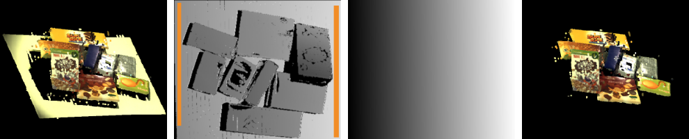
The example remove_background_for_object_location.hdev demonstrates this workflow for a given application.
Arbitrary background shape🔗
In some cases, the background may contain more than just a plane. If it remains steady for all scenes, you can acquire a reference scene (without the wanted objects in it) to subtract it from your actual scenes. Follow these steps to remove a background of arbitrary shape:
- Get the Z-image of the reference scene and your actual scene and subtract them.
* Offline step, performed once:
object_model_3d_to_xyz (XRef, YRef, ZRef, ReferenceScene, 'from_xyz_map', [], [])
* Online steps, performed for every scene:
object_model_3d_to_xyz (X, Y, Z, Scene, 'from_xyz_map', [], [])
sub_image (ZRef, Z, ImageSub, 1, 0)- Apply a threshold and reduce noise to receive a region of interest. Make sure your threshold is lower than the height of the wanted objects.
threshold (ImageSub, Region, 0.5, 1e+10)
connection (Region, ConnectedRegions)
* Remove noise based on shape features, for example, area:
select_shape (ConnectedRegions, SelectedRegions, 'area', 'and', 2000, 1e+10)
union1 (SelectedRegions, RegionUnion)- Reduce your scene by view, using your region of interest.
reduce_object_model_3d_by_view (RegionUnion, Scene, [], [], SceneReduced)Remove bin🔗
The most common approach regarding the removal of the bin in the scene is locating the bin based on a meshed CAD model or isolating the bin from the background as above-mentioned and then to apply a threshold to remove the bin.
Based on meshed CAD model🔗
The bin removal based on a meshed CAD model can be realized based on the following steps:
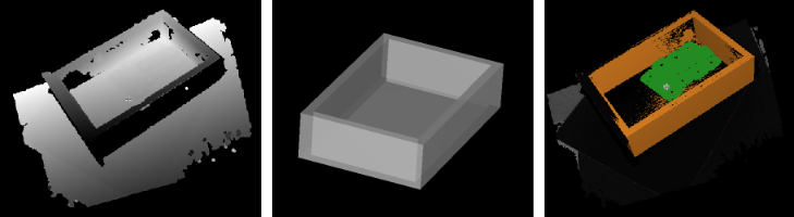
- Create a surface model with the meshed CAD model that models the bin.
create_surface_model (Model, 0.03, 'model_invert_normals', 'true', SurfaceModelID)- Localize the bin.
find_surface_model (SurfaceModelID, Scene, 0.05, 0.2, 0, 'true',[], [], Pose, Score, SurfaceMatchingResultID)- Move the meshed CAD model into the scene.
rigid_trans_object_model_3d (Model, Pose, ObjectModel3DRigidTrans)- Reduce the scene to the bin’s interior. Therefore, subtract the Z-mappings of the scene and the found CAD model, remove the background by applying a threshold and reduce the scene by view, considering the resulting region.
object_model_3d_to_xyz (XModel, YModel, ZModel, ObjectModel3DRigidTrans, 'cartesian_faces', [CameraParam],[0,0,0,0,0,0,0])
object_model_3d_to_xyz (XScene, YScene, ZScene, Scene, 'from_xyz_map', [],[])
sub_image (ZModel, ZScene, ImageSub, 1, 0)
threshold (ImageSub, Regions, 0.001,1)
reduce_object_model_3d_by_view (Regions, Scene, [], [], SceneReduced)
Based on thresholding🔗
In case that no meshed CAD model of the bin is available, the following approach can be used to reduce the scene to the objects inside the bin:
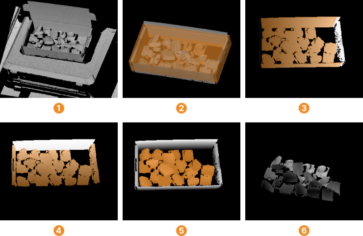
Acquired scene, bounding box, thresholded X-image, thresholded Y-image, intersected regions, reduced scene
-
Estimate the extents of the bin. Now that the scene is reduced to the bin containing the objects to be localized, the bin is estimated approximately with respect to the scene coordinate system (see ).
smallest_bounding_box_object_model_3d (Scene, 'oriented', BoundingBoxPose, Length1, Length2, Length3)
gen_box_object_model_3d (BoundingBoxPose, Length1, Length2, Length3, BoundingBox)- Transform the bin into the center of the estimated smallest bounding box.
pose_invert (BoundingBoxPose, PoseInverted)
rigid_trans_object_model_3d (Scene, PoseInverted, SceneRigidTrans)- Apply a 2D threshold on the X and Y mappings (see and )
object_model_3d_to_xyz (X, Y, Z, SceneRigidTrans, 'from_xyz_map', [], [])
threshold (X, RegionX, -Length1 / 2 * 0.85, Length1 / 2 * 0.85)
threshold (Y, RegionY, -Length2 / 2 * 0.85, Length2 / 2 * 0.85)
Alternatively, you can apply a threshold on X- and Y-coordinates using select_points_object_model_3d.
In this case the next step can be skipped.
- Compute the region of interest by intersecting the X- and Y-mappings and the domain of the scene without background (see the results in and ).
intersection (RegionX, RegionY, RegionIntersection)
intersection (RegionIntersection, SceneDomain, ROI)
reduce_object_model_3d_by_view (ROI, Scene, 'xyz_mapping', [], SceneReduced)