Workflow🔗
In addition to the reference documentation of the surface-based matching operators, here, practical guidance is given on the general proceedings for the workflow of surface-based matching step by step. Note that there are also a number of example programs that can be consulted, showing a variety of surface-based matching approaches.
Creating a surface model🔗
To find your object within a 3D scene you need a 3D model of the object, so its spatial features can be matched.
There are various ways to get a 3D object model, it might, for example, be loaded from a CAD file, or extracted manually from a 3D point cloud.
To apply it for surface-based matching you need to create a surface model for it, using create_surface_model.
If you already have a surface model you can just read the model using read_surface_model.
Note
Besides the 3D point data the 3D object model needs to contain further information, such as point normals, a triangular or polygon mesh, or 2D-mappings. See the operator reference of create_surface_model for details.
For the creation of the surface model, the 3D object model is sampled according to the sampling distance determined in the parameter RelSamplingDistance.
For the refinement of the pose the model is sampled once more, controlled by the generic parameter 'pose_ref_rel_sampling_distance' (see Figure 1).
Note that it is usually not necessary to change these two parameters, as the default values work for a wide variety of models.
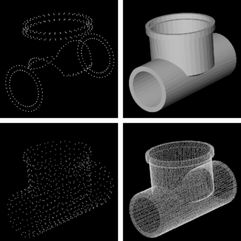
During the surface model creation, you can also train or compute further features of the model, depending on your matching approach.
You can, for example, train the model for 3D edge-support or invert the model normals using generic parameters.
For details refer to the operator reference of create_surface_model.
Finding a surface model🔗
Once the surface model of the object to be matched has been created with create_surface_model, you can use find_surface_model to look for the object in your scene.
The scene is usually acquired by a 3D sensor, whereby certain requirements are put on the data.
A preprocessing step, used to remove the background can enhance the performance significantly.
Note that the workflows of the standard surface-based matching and the edge-supported surface-based matching are the same.
Generally the surface-based matching is performed in three main steps, which are carried out by find_surface_model:
-
Approximate matching:
The approximate poses of the instances of the surface model in the scene are searched. Point clouds are sampled and a subset of key points is defined. For each key point, the optimum pose of the surface model is computed under the assumption that the key point lies on the surface of the object. From all key points, the poses with the best scores are then selected and used as approximate poses. -
Sparse pose refinement:
In this step, the approximate poses found in the previous step are refined by minimizing the distances between the sampled scene points and the planes of the model points. This increases the accuracy of the poses and the significance of the score value. -
Dense pose refinement:
The poses found in the previous steps are accurately refined. This step works similar to the sparse pose refinement and minimizes the distances between all scene points and the planes of the closest model points.
Approximate pose refinement🔗
First, points are sampled uniformly from the scene passed with the parameter ObjectModel3D. The sampling
distance is controlled with the parameter RelSamplingDistance.
Then, a set of key points (see Figure 2) is selected from the sampled scene points. The number of selected key
points is controlled with the parameter KeyPointFraction.
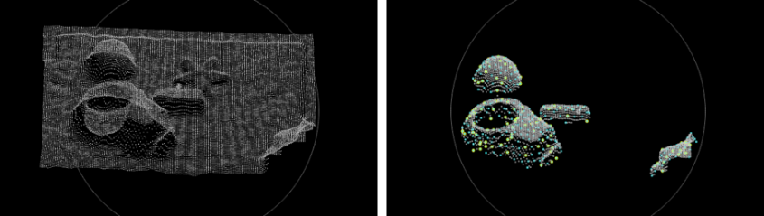
For each selected key point, the optimum pose of the surface model is computed under the assumption that the key point lies on the surface of the object.
This is done by pairing the key point with all other sampled scene points (see Figure 2) and finding the point pairs on the surface model that have a similar distance and relative orientation.
The similarity is defined by the parameters 'feat_step_size_rel' and 'feat_angle_resolution' in create_surface_model.
The pose for which the largest number of points from the sampled scene lie on the object is considered to be the best pose for this key point. The number of sampled scene points on the object is considered to be the score of the pose.
If the model was trained for edge-supported surface-based matching, edges are extracted from the 3D scene, similar to the operator edges_object_model_3d, and sampled.
In addition to the sampled 3D surface, the reference points are then paired with all sampled edge points and similar point-edge-combinations are identified on the surface model.
From all key points the poses with the best scores are then selected and used as approximate poses.
If the pose refinement is disabled, the score described above is returned for each pose in Score.
The value of the score depends on the amount of surface area of the instance that is visible in the scene and on the sampling rate of the scene.
Only poses whose score exceeds MinScore are returned.
To determine a good threshold for MinScore, it is recommended to test the matching on several scenes.
The maximum number of returned poses is set with the generic parameter 'num_matches'.
Note that the resulting poses from this step are only approximate.
The error in the pose is proportional to the sampling rates of the surface model given in create_surface_model, and is typically less than 5% of the object’s diameter.
Sparse pose refinement🔗
The sparse pose refinement uses the sampled scene points from the approximate matching. The pose is optimized such that the distances from the sampled scene points to the plane of the closest model point are minimal. The plane of each model point is defined as the plane perpendicular to its normal.
Additionally, if the model was trained for edge-supported surface-based matching and it was not disabled using the parameter 'use_3d_edges', the pose is also optimized such that the sampled edge points in the scene align with the edges of the surface model.
The sparse pose refinement is enabled by default. It can be disabled by setting the generic parameter 'sparse_pose_refinement' to 'false'.
For large scenes with much clutter, that is, scene parts that do not belong to the object of interest, it is faster to disable the sparse pose refinement.
The score of each pose is recomputed after the sparse pose refinement.
Dense pose refinement🔗
This step works similar to the sparse pose refinement and minimizes the distances between the scene points and the planes of the closest model points. The difference is that:
- A second sampled model of the scene is used (hereby, the number of points depends on the parameter
'pose_ref_sub_sampling'). - If the model was created for edge-supported surface-based matching and it was not disabled using the parameter
'use_3d_edges'(see above), all extracted scene edge points are used for the refinement, instead of only the sampled edge points.
Taking all points from the scene increases the accuracy of the refinement but is slower than refining on the subsampled scene points.
The dense pose refinement is enabled by default, but can be disabled with the generic parameter 'dense_pose_refinement'.
After the dense pose refinement, the score of each match is recomputed.
The threshold for considering a point to be “on” the object is set with the generic parameter value 'pose_ref_scoring_dist_rel' or 'pose_ref_scoring_dist_abs'.
When using the edge-supported matching, the parameters 'pose_ref_scoring_dist_edges_rel' or 'pose_ref_scoring_dist_edges_abs' control the corresponding thresholds for edges.
The final accuracy of the refined pose depends on several factors. The internal refinement algorithm has an accuracy of up to 1e-7 times the size (diameter) of the model. This maximal accuracy is only achieved for best possible conditions.
Factors for the final accuracy are, for example, the shape of the model, the number of scene points, the noise of the scene points, the visible part of the object instance, and the position of the object.
The number of matches to be returned can be controlled by the generic parameter 'num_matches' but also depends on whether the matches exceed the minimum score MinScore.
Visualizing the result🔗
If your matching approach was successful you can check the result by visualizing it with the procedure visualize_object_model_3d (see Figure 3).
Therefore, display your model in the scene after translating and rotating it according to the result pose(s) that are returned by find_surface_model or find_surface_model_image in the parameter Pose.
If used for the matching, you can also display the 3D edges in this visualization.
rigid_trans_object_model_3d (ObjectModel3D, Pose, ObjectModel3DRigidTrans)
visualize_object_model_3d (WindowHandle, [Scene, ObjectModel3DRigidTrans], [], [], [], [], [], [], [], VisPose)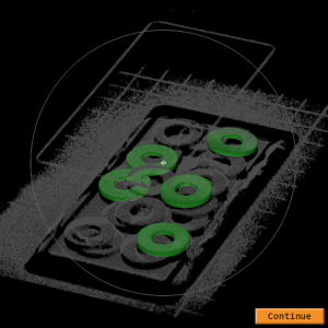
visualize_object_model_3d to inspect your results (green). Data requirements🔗
XYZ-mappings🔗
XYZ-mappings are XYZ-images that map 3D coordinates into 2D coordinates, that is, the X-coordinates are encoded as gray-values in the X-image, the Y-coordinates are encoded as gray-values in the Y-image and the Z-coordinates are encoded as gray-values in the Z-image (see example in Figure 4). As the order of the 3D coordinates might be important for further processing steps, it is coherently determined by the 2D image coordinates.

When handling 3D object models, for instance when a model is prepared for surface-based matching, using 2D-mappings instead of the point cloud data can increase speed and robustness distinctly.
In the context of surface-based matching, mappings are especially used to compute normal vectors and 3D edges.
If the model is trained for edge-supported surface-based matching, mappings are explicitly required for the scene.
The mappings can be created using the operator object_model_3d_to_xyz.
Surface normal vectors🔗
A point normal is a normalized vector attached to the point coordinate. It defines the tangent plane to the surface on the point. In HALCON point normals can be computed with:
-
surface_normals_object_model_3dandsmooth_object_model_3d
Note thatsmooth_object_model_3dredistributes the points to describe a smoother surface manifold. -
sample_object_model_3d
The operatorsample_object_model_3dwith the mode'fast_compute_normals're-computes normal vectors if a mesh or mappings are available. Therefore, any available normal vectors are ignored in those cases.
Note
For robust and successful matching results, it is important that the normals of the model and the normals of the scene both point approximately in the same direction. Furthermore, for edge-supported surface-based matching, model and scene normals need to point inwards.
find_surface_model and find_surface_model_image ignore any polygonal or triangular mesh data, points and normals are used instead.
If the scene does not have normals, they will be computed and aligned based on the parameter 'scene_normal_computation' of find_surface_model and find_surface_model_image.
Note that, if the model was trained for edge-supported surface-based matching, the normals are computed from the mappings of the scene, regardless of whether there are normals provided already or not.
For the matching, it is recommended to use scenes that contain normals or XYZ-mappings.
Check the normals, among various further features, of your scene by using the procedure debug_find_surface_model.