Workflow🔗
Depth from focus requires a focus stack of images, i.e., images that each have a different distance to the object and in which, therefore, different pixels are sharp. Depth from focus is then applied to this focus stack returning a sharp image, i.e., an image containing only gray values from focused, sharp pixels as these are the relevant pixels for DFF, as well as a depth image showing the three-dimensional shape of the object that is inspected.
Acquiring images🔗
Rules for high image quality🔗
- Avoid overexposure.
- Avoid reflections.
- Use a camera with a wide dynamic range.
- Use direct illumination - preferably from several directions.
- Use a camera with low noise.
- The maximum number of images is limited by camera noise. Taking more images to cover the whole object only improves the precision of the reconstruction to a certain degree which is, amongst others, limited by the camera noise.
- As a rule of thumb, the minimum number of images that should be acquired for DFF is 10 and the maximum number is about 150. While 10 images can be just sufficient for measuring (depending on the required accuracy), more than 150 images will usually not improve accuracy any more. The corresponding formula would be:
with \(h\) being object height and \(DOF\) being depth of field.
Rules for best result with your system setup🔗
- Cover the whole distance range.
- Let the depth of field areas overlap.
- The distance between the light source and the object should remain constant.
- The optical system should enable an orthographic projection (parallel projection), i.e., use a telecentric lens or a microscope in your system setup. If this is impossible, consider using a standard lens.
- The axis of the focusing displacement must be parallel to the optical axis of the lens, otherwise the object shifts laterally within the focus sequence.
- Do not move the camera or object in x or y direction. DFF does not work on an object that is, e.g., moving on a conveyor belt between images or an object that is moved by any kind of vibration or agitation.
Note that the quality of your measuring results does depend on the quality of the input images and you should therefore aim to achieve the highest possible quality.
Using depth from focus🔗
This section describes an example application where the task is to test if a PCB board is covered by an appropriate amount of soldering paste.
This inspection is performed with DFF and can be viewed in the HDevelop example program %HALCONEXAMPLES%\hdevelop\Applications\Measuring-3D\measure_solder_paste_dff.hdev (for more information also refer to the example %HALCONEXAMPLES%\hdevelop\Applications\Measuring-3D\measure_bga_dff.hdev which is a similar program showing how a ball grid array is measured with DFF).
An image sequence is acquired and a height map of the single circuits and pads is calculated.
This way parts that have no soldering paste can be identified as well as those that are covered sufficiently.
First all necessary images for the focus series have to be acquired and combined to a multi-channel image with the operator channels_to_image.
read_image (ImageArray, 'dff/focus_pcb_solder_paste_' + Sequence$'02')
channels_to_image (ImageArray, Image)
Then, depth from focus is performed, a depth map is calculated and all sharp gray values are selected.
Both results can be used for further processing.
Depth from focus is performed with the HALCON operator depth_from_focus.
The channel number is returned for each pixel together with a confidence value, which is an indicator for the quality of the distance value.
Pixels with the best focus are chosen.
The method can be selected with the parameters Filter and Selection.
It is striking that the images are very dark, when looking at the images in the example %HALCONEXAMPLES%\hdevelop\Applications\Measuring-3D\measure_solder_paste_dff.hdev.
They have been acquired like this on purpose to avoid overexposure.
However, to improve the visibility of the object’s surface in the image, the operator scale_image enhances the sharpness, scale_image_max spreads the gray values in the image to improve visibility despite of the darkness.
median_rect suppresses unwanted outliers.
depth_from_focus (Image, Depth, Confidence, 'bandpass', 'next_maximum')
select_grayvalues_from_channels (Image, Depth, SharpenedImage)
scale_image (SharpenedImage, ImageScaled, 4, 0)
scale_image_max (Depth, ImageScaleMax)
median_rect (ImageScaleMax, DepthMean, 25, 25)
Finally, the results - the sharp image as well as the 3D plot - are displayed as shown in Figure 1.
A sharp image is reconstructed by selecting the gray value of each pixel that is in focus for each coordinate using the depth image as index table.
The focus stack and the depth image are used as input to reconstruct a focused image using the parameters MultiChannelImage, IndexImage and Selected.
Sharp gray values can be identified by high frequencies, i.e., high edge amplitudes in the image, i.e., where the gray-value information changes quickly.
For each sharp pixel, a confidence score is returned.
The amount of sharpness defines the score.
Furthermore, a 3D plot of the object in the image is calculated which is helpful for detecting defects.
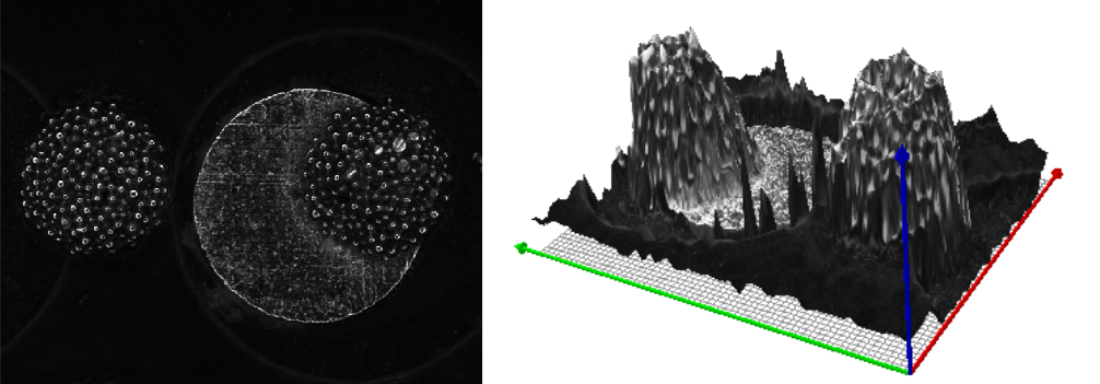
dev_open_window (0, Width * 0.7 + 5, Width * 0.7, Height * 0.7, 'black', \
WindowHandle3D)
dev_set_paint (['3d_plot', 'texture'])
compose2 (DepthMean, ImageScaled, MultiChannelImage)
dev_display (MultiChannelImage)
Measuring volume🔗
In contrast to stereo, the height information is not calibrated for depth from focus.
The values in the height image are indices of input images.
To measure a real world height or volume, the distance in between these images must be known.
The easiest case is that images are taken with the same movement z.
If two coordinates differ by an index value of n, the real world distance will be \(z \times n\), with the unit of z.
The unit in x and y, i.e., the size of a pixel must be known.
Make sure that all dimensions are given in the same unit.
Volume can be determined with the operator area_center_gray by adding up the pixel values which are equal to the height values.
The resulting value must be multiplied by x, y and z.