Setup🔗
Camera🔗
Recommended camera setup and adjustments🔗
As performance of depth from focus for your application depends on the used lens, the depth of field and the precision of the movements, it is important to use the right camera with the right adjustments. Please read our recommended camera setup and adjustments for the best results:
-
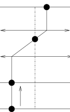
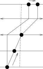
If possible, use a camera with a telecentric lens. In order to perform depth from focus, a camera with a telecentric lens or an almost telecentric lens, e.g., a microscopic imaging system, will produce the best results. Only a telecentric lens enables you to take images with exactly the same field of view at different focus positions. This is important because depth from focus uses image coordinates and for each pixel finds the image in which it is displayed sharply. Only in images taken with a telecentric lens, those pixel are comparable, i.e., in the same position. Therefore, DFF is a good method for measuring small objects, like, e.g., microelectronic workpieces. Good results have been achieved, for example, when performing DFF with the XENOPLAN telecentric lens series by Schneider-Kreuznach. Note however that even when using a telecentric lens, aberration - the effect that not all pixels are in focus on a planar surface - can occur. Aberration influences the accuracy of DFF and should be calibrated. It is also possible, though not recommended due to the reasons mentioned before, to use DFF with a standard lens. A problem that is related to the lens is the correspondence problem. This refers to effect that the position of the pixels outside the optical axis shifts when the distance is changed during image acquisition. Those planes that lie close to the border of the field of view as well as those that lie diagonal to the optical axis are affected most. A small depth of field reduces the effect for planes with other directions. The correspondence problem results in wrong focus distances in the depth image. This effect is minimal when using a telecentric lens. For telecentric lenses, it is important that the movement causing a change of focus is applied parallel to the optical axis. For more information about this effect see Table 1.
-
Use mirrors to obtain focus images. For DFF, mirrors are a very good solution because they can be moved very quickly and accurately and - if necessary - can be replaced easily and inexpensively. Moving the camera may be harmful to the camera sensor which suffers under the vibrations. Moving the object might be difficult as the object is probably located on a conveyor belt. All movements for DFF have to be performed very precisely. What such a setup with camera and mirrors can look like is shown in Figure 1. Note that the focus should only be moved along the optical axis.
-
Use a low depth of field to achieve a higher accuracy. This requires, however, more images at different focus positions. In contrast, large distances between the images require a higher depth of field and lead to a less precise height reconstruction. A low depth of field requires - as stated before - images at various focus positions.
-
Use a high aperture. The aperture needs to be as open as possible as this reduces the depth of field which is responsible for a higher precision as mentioned before. The highest possible precision is, therefore, limited by the depth of field.
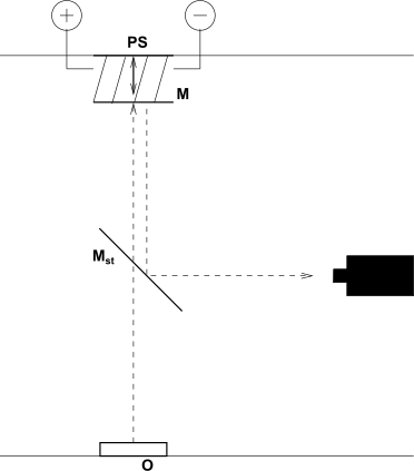
Linear piezo stage \(PS\)
Mirror \(M\)
Semi-transparent mirror \(M_st\)
Object \(O\)
 |
 |
|---|---|
| A change of focus is applied parallel to the optical axis, which is good. | If the focus is not changed parallel to the optical axis, a lateral offset occurs |
Acquire measurement range🔗
There are four rules that define how the measurement range can be acquired.
First rule: The distance range has to exceed the height of the measure object.
Second rule: The range in which the image part changes from blurred over sharp to blurred should be approximately five images (as depicted in Figure 2). Otherwise, areas of the object’s surface cannot be determined correctly and, therefore, cannot be measured precisely.
Third rule: As the depth of field of the used lens is fixed, the minimum number of focus positions has to exceed:
with \(r_f\) being the focus range in meters and \(DOF\) being the depth of field of the used lens.
The reason for this is the shifted depth of field area of the lens. This shift needs to be smaller than the depth of field of the lens so that the depth of field areas from two successive images can overlap. The more those images overlap, the higher the achieved precision. The downside is an increased runtime due to the high number of images. You cannot, however, increase precision indefinitely as it is also limited by the camera noise. The smaller the overlap, the smaller the achieved precision, the shorter the runtime.
Fourth rule: If there is a limit to the number of images that can be acquired, for example, because you have limited runtime, the depth of field of the used lens needs to be increased (e.g., by closing the aperture of the lens).
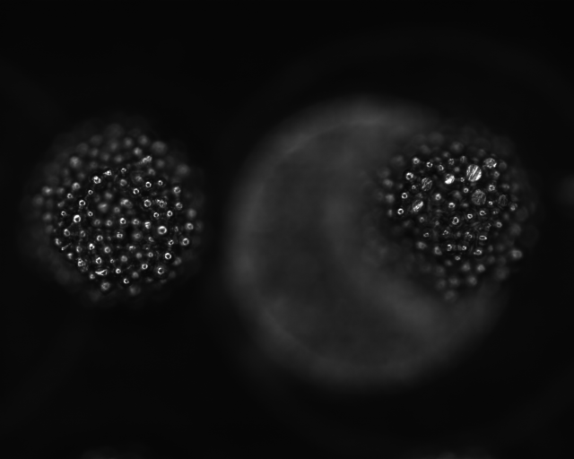
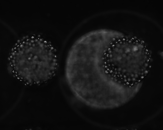
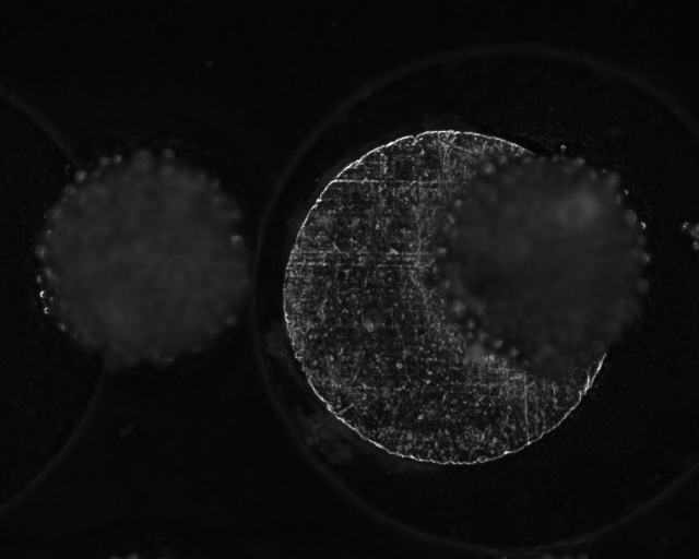
Images from a focus stack can be viewed in Table 2.
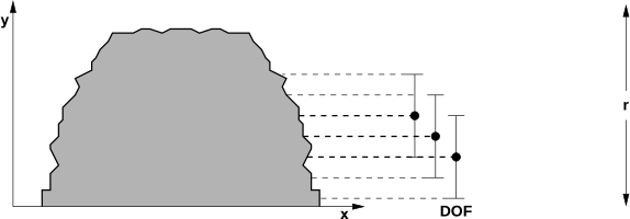
Measurement range \(r\)
Depth of field \(DOF\)
 |
 |
 |
|---|---|---|
| Focus on the top of the object. | Sharp at a medium height. | Sharp in the background |
Depending on the direction of image acquisition, i.e., from the camera or towards the camera, the result of the measurement is either a distance image or a height image.
Illumination🔗
Choosing illumination🔗
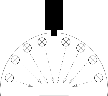
In order to enhance the surface texture of the object, direct illumination is needed. At the same time, reflections have to be minimized. Therefore, coaxial and light-field lighting would not work. A suitable lighting could be an illumination from various directions, as depicted in Figure 3, because lighting that comes from different directions enhances the structure very well and also causes few reflections. As an alternative dark-field lighting is also possible, because the low angle enhances the surface structure - it does, however, result in an image that has quite dark parts in some areas. Other illumination setups can be used as long as the lighting enhances the surface texture and causes as few reflections as possible. A suitable illumination, therefore, highly depends on the application object’s features.
Overexposure🔗
Overexposure is an illumination-connected problem that may occur and reduce the accuracy of the resulting image.
It leads to a loss of information in the overexposed region which then reaches saturation (a gray value of 255).
Furthermore, overexposure causes the detection of false sharp pixels in blurry areas which are the result of high frequencies between saturated image areas and blurry areas.
The results of overexposure are visualized in Figure 4.
In order to avoid overexposure, it is recommended to take darker images for your measurements and improve visualization with the operators scale_image and scale_image_max (see this example).
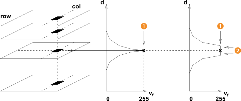
Best focus point
False edges
\(v_f\) focus value for each pixel
\(d\) depth
Object🔗
In order to successfully perform DFF, it is important to know your application object.
First of all, DFF is a practical method for any small object with textured surface. For objects that are larger than that, there are several other 3D methods available like binocular stereo. DFF can, however, still be used for very high objects that would usually require a very high number of images and thus slow down the measuring process a lot. If the height of such an object is required there are two possibilities of gaining these measuring results.
- One possibility is to take a certain number of images (e.g., 10) that depict the bottom of the object, then also take a certain number of images showing the top of the object. Because you know the distance between the highest image that is taken of the bottom of the object and the first image taken of the top of the object, you can just add this height to the images taken of the top of the object.
- Another possibility is to acquire two sequences: one has to be taken around the bottom of the object and another one at the top of the objects. Within each of the sequences the sharpest level is detected. As the movement of the motor that determines the acquisition of images at different focus levels is known, the distance between those images can be calculated.
Two image sequences are acquired, one taken around the highest point of measurement and one sequence around the lowest point of measurement. Once, the sharpest pixels at the highest and lowest point are found, the height can be calculated.
Regular (passive) DFF can be used for objects with a textured surface. Fortunately, small objects mostly have a structured surface when observed at a suitable magnification. The exception are perfectly polished, i.e., specular surfaces.
If there is very little texture on the object, it is possible to still perform the so-called active depth from focus. Active DFF compensates for the missing surface structure by projecting a texture on the object. When performing active DFF, it is possible to produce focus images with the projector. It is, however, necessary that - for every image that is taken - the depth of field of the camera is conform with the depth of field of the projector. Active DFF does work for objects with little texture on their surfaces, it does not work for reflecting surfaces, though.