About poses🔗
A pose describes a rigid 3D transformation, that is, a transformation consisting of an arbitrary translation and rotation.
In HALCON, a pose is a tuple with seven parameters:
Three parameters specify the translation (TransX, TransY, and TransZ) and three parameters describe the rotation (RotX, RotY, and
RotZ).
The last parameter codes the order of the translations and the rotations (as well as the direction of rotation).
More Info
For more information about these parameters, see the documentation of create_pose and the sections in 3D vision.
3D poses can be interpreted in two ways:
-
A pose can describe the position and orientation of one coordinate system relative to another (for example, the pose of a part’s coordinate system relative to the camera coordinate system, in short: the pose of the part relative to the camera).
-
A pose can describe how coordinates can be transformed between two coordinate systems (for example, to transform points from part coordinates into camera coordinates).
A pose that transforms point coordinates from coordinate system 1 (cs1) to coordinate system 2 (cs2) is denoted as \(\mvPoseVar{{cs2}}{{cs1}}\)
The corresponding transformation of a point given in cs1 (\(\mvVectorVar[cs1]{p}\)) into cs2 (\(\mvVectorVar[cs2]{p}\)) is denoted as
Note
Not the pose (as a tuple) but the transformation described by this pose is used for the multiplication and the above notation is only used for readability.
Hence, the pose \(\mvPoseVar{{cs2}}{{cs1}}\) describes the rigid transformation that is represented by the homogeneous transformation matrix
\(\mvHomMatrixVar{}{}(\mvPoseVar{{cs2}}{{cs1}}) = \mvHomMatrixVar{cs2}{cs1}\)
For more information, see the documentation of create_pose, for example.
Consequently, the pose \(\mvPoseVar{{cs2}}{{cs1}}\) describes the transformation of points from cs1 into cs2.
As mentioned above, it also describes the transformation of the coordinate system itself, however, in reverse order:
\(\mvPoseVar{{cs2}}{{cs1}}\) describes how coordinate system 2 must be transformed to obtain coordinate system 1, and hence, the pose of coordinate system 2 relative to system 1.
With this notation, poses can easily concatenated like homogeneous matrices, for example:
Such a concatenation can be done using, for example, pose_compose.
Transformations using 3D poses🔗
Homogeneous transformation matrices are a very elegant means of describing transformations, but their content, that is, the elements of the matrix, are often difficult to read, especially the rotation part. This problem is alleviated by using so-called 3D poses.
A 3D pose is nothing more than an easier-to-understand representation of a rigid transformation: Instead of the 12 elements of the homogeneous transformation matrix, a pose describes the rigid transformation with 6 parameters, 3 for the rotation and 3 for the translation: (TransX, TransY, TransZ, RotX, RotY, RotZ).
The main principle behind poses is that even a rotation around an arbitrary axis can always be represented by a sequence of three rotations around the axes of a coordinate system.
In HALCON, you create 3D poses with create_pose.
To transform between poses and homogeneous matrices you can use hom_mat3d_to_pose and pose_to_hom_mat3d.
Sequence of rotations🔗
However, there is more than one way to represent an arbitrary rotation by three parameters.
This is reflected by the HALCON operator create_pose, which lets you choose between different pose types with the parameter OrderOfRotation.
If you pass the value 'gba', the rotation is described by the following chain of rotations:
You may also choose the inverse order by passing the value 'abg':
For example, the transformation discussed in the previous sections can be represented by the homogeneous transformation matrix:
The corresponding pose with the rotation order 'gba' is much easier to read:
(TransX = \(x_t\), TransY = \(y_t\), TransZ = \(z_t\), RotX = \(0°\), RotY = \(90°\), RotZ = \(-90°\) )
The rotation can also be described by the sequence \(R_z(-90°) \cdot R_x(-90°)\).
Thus, the transformation can also be described by the following pose with the rotation order 'abg':
TransX = \(x_t\), TransY = \(y_t\), TransZ = \(z_t\), RotX = \(-90°\), RotY = \(0°\), RotZ = \(-90°\) )
HALCON operators
Below, the relevant HALCON operators for dealing with 3D poses are briefly described.
-
create_posecreates a pose. -
hom_mat3d_to_poseconverts a homogeneous transformation matrix into a pose. -
pose_to_hom_mat3dconverts a pose into a homogeneous transformation matrix. -
convert_pose_typechanges the pose type. -
write_posewrites a pose into a file. -
read_posereads a pose from a file. -
set_origin_posetranslates a pose along its “new” axes. -
pose_invertinverts a pose. -
pose_composemultiplies two poses, that is, it sequentially applies two transformations (poses).
How to determine the pose of a coordinate system🔗
The previous sections showed how to describe known transformations using translation vectors, rotation matrices, homogeneous transformation matrices, or poses. Sometimes, however, there is another task: How to describe the position and orientation of a coordinate system with a pose.
Figure 1 shows how to proceed for a rather simple example. The task is to determine the pose of the world coordinate system relative to the camera coordinate system.
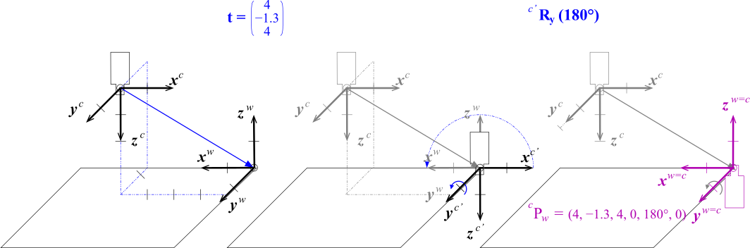
Camera coordinate system: \((x^c, y^c, z^c)\)
Intermediate coordinate system: \((x^{c'}, y^{c'}, z^{c'3'})\)
World coordinate system: \((x^w, y^w, z^w)\)
In such a case, we recommend to build up the rigid transformation from individual translations and rotations from left to right. Thus, in Figure 1 the camera coordinate system is first translated such that its origin coincides with that of the world coordinate system. Now, the y-axes of the two coordinate systems coincide; after rotating the (translated) camera coordinate system around its (new) y-axis by \(180°\), it has the correct orientation.